
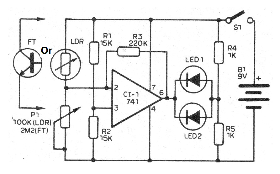
This circuit uses as indicators two LEDs that must be cleared when the set point on the potentiometer scale is reached.
We can use it in optics experiments, in the physics lab and in comparing color tints and lighting systems.
As sensors can be used LDRs or photo-transistors and the power is made with battery of 9 V, with a very low consumption.
In figure 1 we have the complete circuit of this photometer.
This circuit may be mounted on a printed circuit board with the array of components shown in Figure 2.
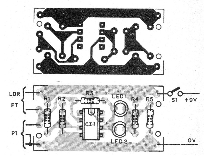
On assembly, note the position of the integrated circuit, the phototransistor and the polarity of the LEDs.
The resistors are 1/8 W with 20% or less tolerance and the LDR is of the ordinary round type.
To use, aim the sensor at a light source and slowly rotate the potentiometer until both LEDs extinguish.
By calibrating the potentiometer scale, we can read the value of the measured light intensity.
Material list
CI-1 - 741 - operational amplifier
LDR - Common LDR
FT- any photo-transistor
LED1, LED2 - Common red LEDs
B1 - 9 V - battery
S1 – On-Off switch
P1 - 100 k ohms - potentiometer
R1, R2 - 10 k ohms - resistors - brown, black, orange
R3 - 220 k ohms - resistor - red, red, yellow
R4, R5 - 1k ohms - resistors - brown, black, red
Several:
Battery connector, printed circuit board, mounting box, wires, solder, etc.


