
This circuit generates a low power signal in the upper VHF range. The signal can be picked up at a suitable receiver within a few meters and even on a VHF television between channels 11 and 13.
On a regular television, the signal, because it is not modulated, will make the screen dark and possibly cause the program to be changed. An application of this circuit is as the basis for a TV test generator, since modulation with audio generates horizontal bars.
In figure 1 we have the complete diagram of the oscillator and in figure 2 the assembly in a small terminal plate. The original porcelain trimmer can be exchanged for a modern plastic equivalent.
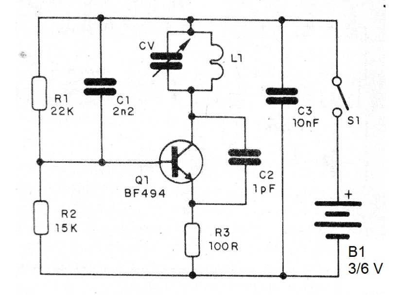
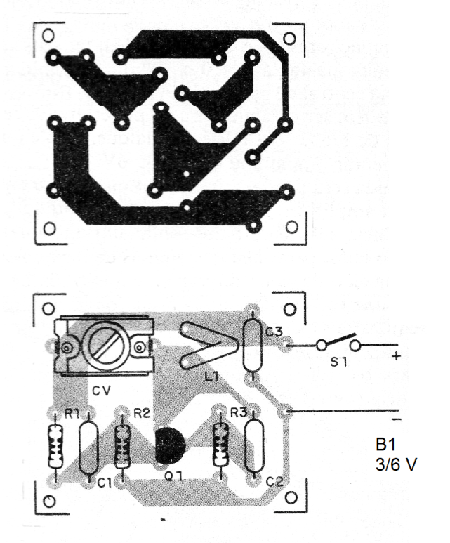
The frequency-determining coil L1 consists of 1 strand of 22 AWG unshaped wire approximately 1 cm in diameter. The trimmer can be 10 to 20 pF of maximum capacitance. It may optionally be replaced by a ceramic capacitor of 1 to 2.2 pF.
We do not recommend another assembly technique because it is a very high frequency circuit. Eventually a small 10-15 cm antenna can be attached to the transistor collector.
Material list
Q1 - BF494 - RF NPN transistor
CV- trimmer from 10 to 10 pF - see text
L1- coil - see text
B1-3 or 6V- 2 or 4 small cells
S1- Single switch
R1 - 22k ohm x 1/8 W - resistor - red, red, orange
R2 - 15k ohm x 1/8 W- resistor - brown, green, orange
R3 - 100 ohm x 1/8 W - resistor - brown, black, brown
C1- 2n2 - ceramic capacitor
C2 - 1 pF - ceramic capacitor
C3-10 nF- ceramic capacitor
Miscellaneous: printed circuit board, battery holder, mounting box, wires, solder, etc.


