
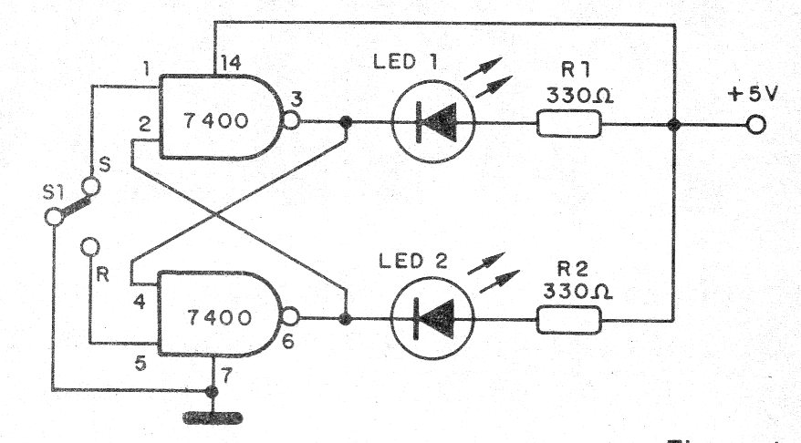
This circuit is indicated for demonstrations of the operating principle of an R-S flip-flop with TTL technology. The circuit is based on two of the four NAND ports available on a 7400, easy to obtain and low cost.
The circuit power must be supplied with a voltage of 5 V and the indication of operation is obtained through LEDs.
This circuit, in fact, is a 1-bit memory, and several of them can be used to demonstrate binary numbering or memorize information in a single circuit.
The state combination is made by taking inputs 1 and 5 to the low level, ie by grounding via an external switch.
In figure 1 we have the complete diagram of the flip-flip TTL.
The assembly may be made in a contact array, or even on a printed circuit board with the array of components shown in Figure 2.
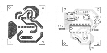
Remember that the 7400 has two more NAND ports that can be used in a second flip-flop or memory cell.
The resistors are 1/8 W and the LEDs can be different colors.
To use the device, simply switch the switch S1 to the R or S position according to the desired switching.
Material list
CI-1 - 7400 - TTL integrated circuit
LED1, LED2 - Common LEDs of any color
R1, R2 - 330 ohms x 1/8 W - resistors - orange, orange, brown
S1 - Switch - 1-pole x 2 positions
Several:
Printed circuit board, 5V supply, wires, solder, etc.


