
ART1388S ART2368
(*) This accident occurred when a medical device was inadvertently disassembled and the radioactive substance leaked, contaminating many people who came into contact with it.
What characterizes a radioactive substance is its slow decay (transformation) with the emission of subatomic particles, some of which are highly penetrating. The radioactivity of certain substances can last for years or even thousands of years, measured by a factor called "half-life".
Thus, we say that a radioactive substance has a "half-life" of 50 years, when this time interval is needed for a certain quantity of it to be reduced to half.
It is clear that the substance will not disappear in the following 50 years, with the other half being reduced to zero. What happens is that after another 50 years, half will be reduced to 1/4.
Note that, no matter how much time passes, the substance does not reduce to zero, but always to half of half in a process that leads us to an exponential curve as shown in Figure 1.
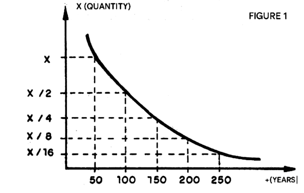
Radioactive substances are formed by unstable atoms that "explode" from time to time, emitting "shards" which are the subatomic particles that we call radiation.
A body that has atoms exploding in a continuous process, leading to its annihilation over time, is called radioactive. The main types of particles emitted by a radioactive body are three, as shown in Figure 2.
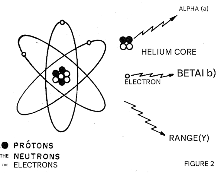
Alpha (α) particles are the heaviest, as they consist of helium nuclei (two protons and two neutrons) with little penetration and a positive electric charge. Even a thin sheet of aluminum can block these particles.
More penetrating are beta (β) particles, which consist of strongly accelerated electrons (negative) that can pass through even thick objects. However, the most penetrating of all are gamma (γ) particles, which consist of electromagnetic radiation with very short wavelengths and can even pass through large obstacles such as concrete and lead walls many centimeters or even meters thick!
The big problem for our health is that these particles, when they hit the atoms of the organic substances that make up our body, can destroy them. This means that the cells in our body where these atoms are located can suffer a serious chemical imbalance and thus be led to death. The thousands and thousands of particles emitted by the radioactive body then do a slow but constant job of destruction, killing the cells in our body. (Figure 3)
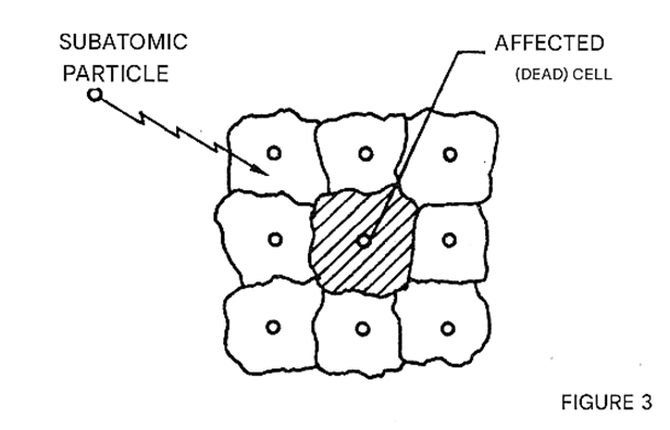
The cells responsible for defending our bodies, tasked with producing new cells to replace those that die, are the most affected. As a result, we become completely defenseless, and death can occur quickly. In short, the best protection against radiation is to avoid exposure to it. If the exposure is short, generally nothing happens because the body still "reacts" by reproducing any cells that are killed.
Devices called "dosimeters" are carried by people who work in environments that exhibit radioactivity and allow them to know the "dose" of radiation received and thus prevent it from reaching dangerous levels. The detectors we have described are of the conventional type that use "Geiger-Müller" tubes, serving to detect the presence of ionizing particles (possessing electrical charges) such as Alpha and Beta particles. (The article is from 1987. There are other types of detectors today).
We will give three versions, one for use in laboratories powered by the local network and two for portable use (with batteries).
Of the portable ones, one has an audible indication of the presence of radiation and the other uses an instrument. The circuits are simple and can eventually be improved to be used in more advanced research such as particle counting, alarm triggering, etc.
HOW THEY WORK
The "heart" of our detectors is a "Geiger-Müller" tube, whose structure is shown in Figure 4.
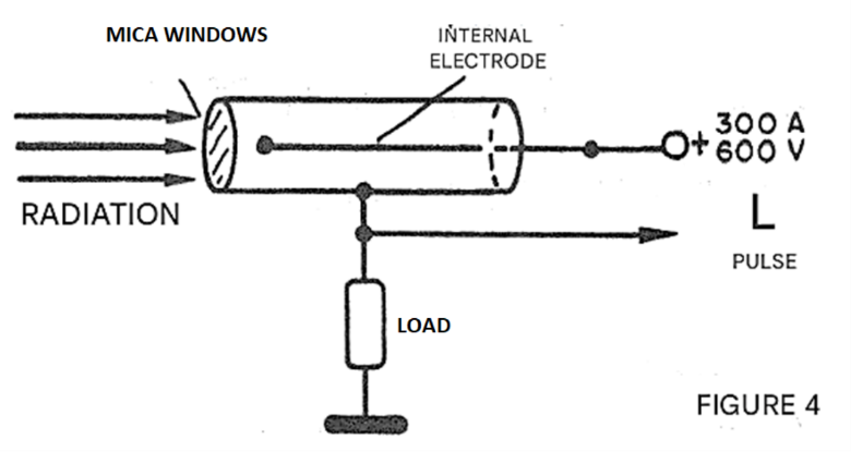
This tube consists of a thin-walled tube filled with a low-pressure gas and featuring a mica window to allow the passage of less penetrating radiation, which is that of alpha particles. We subject this tube to a high voltage, between 300 and 800 volts, so that the gas inside is close to the ionization point. Under these conditions, there is no current flowing between the electrodes of the tube.
When an ionizing radiation particle enters the tube and passes through the gas, the gas shortly becomes current conducting, thus providing a current pulse. This pulse can then be fed to the following electronic circuits. We have two possibilities for these circuits: in a sound detector, it will suffice to connect headphones or an audio amplifier stage with a loudspeaker.
Each pulse corresponding to a radioactive particle will produce a perfectly audible "click" or snap. The number of clicks allows us to determine whether a material is radioactive or not, or whether a location is contaminated or not. The frequency of the clicks (scintillations) even allows us to measure the radiation.
Another possibility is to connect an integrator to the tube output and thus have a sum of the pulses that will be indicated on an instrument. The instrument can then be calibrated in terms of Roentgen. This unit can be defined as the amount of radiation produced in 1 cm³ of dry air at 0°C and 760 mmHg pressure by a number of ions equivalent to one electrostatic unit of each pole (2 x 10⁹ ion pairs).
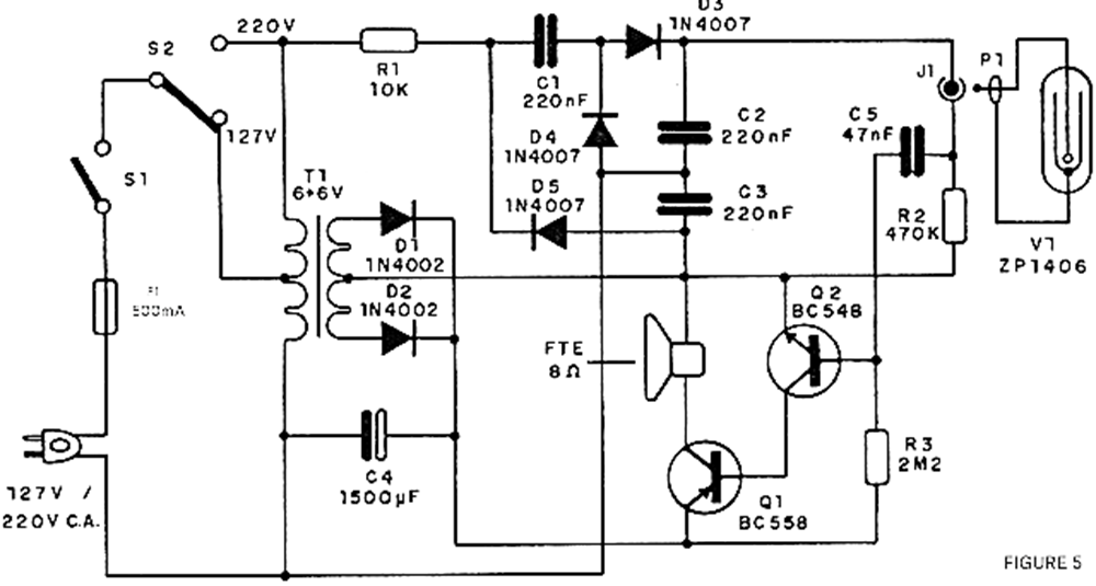
For our circuits, we use a vacuum tube that needs at least 300 V to operate. In the case of mains power, we obtain the high voltage from an autotransformer connected to a voltage tripler. Since the current is very low, the tripler works with low-value capacitors and the tube load is a 470 kΩ resistor.
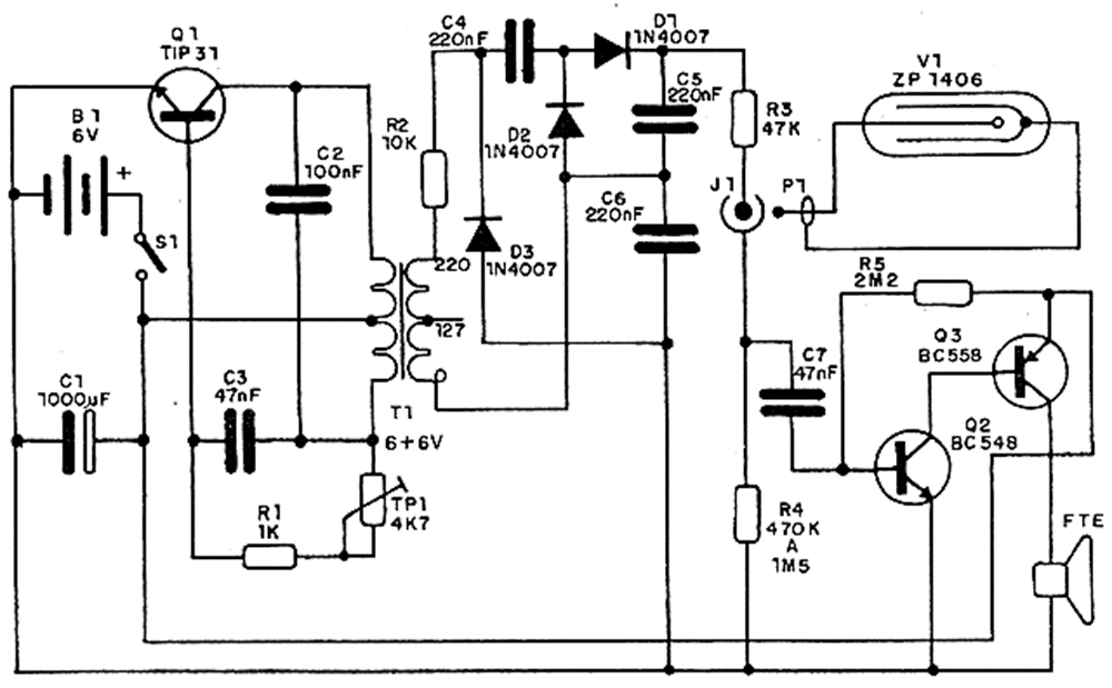
In the case of battery power, we use a transistorized inverter with relatively low current consumption and a transformer that applies the signal to a tripler, resulting in a voltage between 300 and 600 V for the tube. The audio amplification and measurement stages are conventional, using transistors. The indicator is a VU meter.
ASSEMBLY
CIRCUIT 1: DETECTOR FOR MAINS POWER SUPPLY
Figure 5 shows the complete diagram of this version;
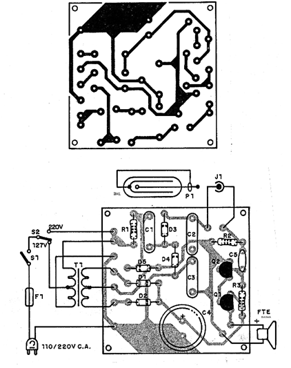
The printed circuit board assembly is shown in Figure 6.
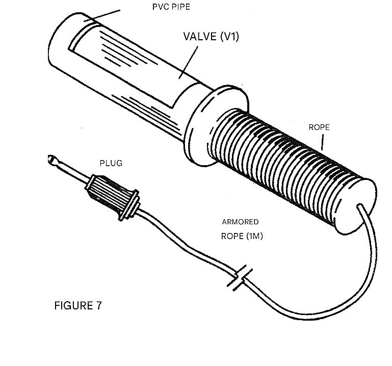
We must take a moment here to discuss the assembly of the ZP1406 type Geiger-Müller tube (Philips). This tube is extremely delicate and should not be handled roughly, as any impact can damage its mica window (which is very fragile). In our assembly, we opted for a padded PVC tube with a rubber cable of the bicycle handlebar type, which can be purchased in supermarkets. The wire connecting to the circuit is a coaxial cable with a plug.
Figure 7 shows details of the sensor connection.
The transformer used is a 110/220 V primary type with a 6 + 6 V x 100 mA or more secondary. The secondary is used to power the transistorized amplifier. Capacitors C1, C2, and C3 are for high voltage, at least 600 volts, and can be metallized polyester or equivalent; their value is not critical.
Values between 150 nF and 470 nF can be used without problems.
For diodes DS, D4, and D5, BY127 capacitors in all three versions can be used as equivalents. Capacitance C4 should have a working voltage between 12 and 16 V, and the resistors are 1/8 or 1/4 W.
TESTING AND USE
For testing, it is not necessary to have any radioactive substance, as nature itself provides the radiation. In fact, the Earth is constantly being bombarded by cosmic rays, and some of them manage to reach the surface.
When one of these rays hits the Geiger counter, which occurs at intervals on the order of a few tens of seconds, a click will be heard in the speaker. Leave the device on for a few minutes and observe if at least one or two clicks are heard. If this happens, the device is working properly, as it is detecting cosmic rays. To use it, simply go into the field and bring the sensor close to the "suspected" substance. The production of clicks indicates the presence of radiation.
LIST OF MATERIALS
V1 - Geiger-Müller tube ZP1406 or equivalent (Philips)
Q1 - BC0558 or equivalent – PNP transistor
Q2 - BC548 or equivalent – NPN transistor
D1, D2 - 1N4002 or equivalent - rectifier diodes
D3, D4, D5 - 1N4007 or BY127 – rectifier diodes
S1 - Simple switch
S2 - 1-pole x 2-position switch
F1 – 500 mA - fuse
T1 - 110/220 V x 6 + 6 V x 100 mA or more current transformer
FTE - small 8 ohm speaker
C1, C2, C3 - 150 to 470 nF x 600 V - polyester capacitors (recommended value = 220 nF)
C4 – 1500 uF x 12 V - electrolytic capacitor
C5 – 47 nF - ceramic or polyester capacitor
R1 – 10 kΩ - resistor (brown, black, orange)
R2 – 470 kΩ - resistor (yellow, violet, yellow)
R3 - 2M2 Ω - resistor (red, red, green)
Miscellaneous: mounting box, wires, printed circuit board, shielded cable, power cable, etc.
CIRCUIT 2 – PORTABLE DETECTOR WITH AUDIBLE INDICATION
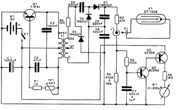
This portable circuit can be powered by medium or large batteries and provides a loudspeaker indication. Figure 8 shows the complete diagram, which is quite similar in the detector section to the previous version.
The printed circuit board is shown in Figure 9.
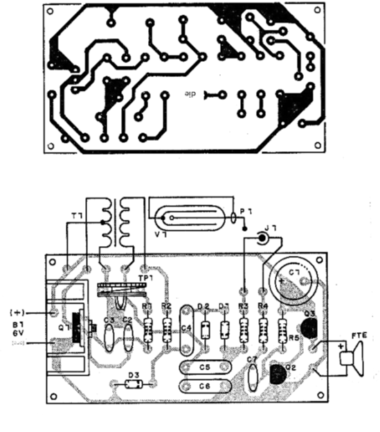
For the inverter, we use a 6 + 6 V transformer with 100 to 250 mA current and a 110/220V primary, with the center tap (110/127V) not used. The TiP31 transistor should be mounted on a small heat sink. Capacitor C3 can be polyester or ceramic, and C1 should have a working voltage of at least 6 V.
The other components, for the high-voltage detector and amplifier, are the same as in the previous version. The sensor assembly should also be done as in the previous version. For the batteries, an appropriate holder should be used, and the case for mounting should be chosen according to their size.
TESTING AND USE
Place the batteries in the holder and connect a multimeter to R2 (220 V output of the transformer) on the alternating voltage scale that allows measuring at least 200 V. Adjust TP1 so that the reading is at least 120 V. Note that this value is not real, as the multimeter represents a load that reduces the voltage.
In open circuit or with the multiplier only, this voltage increases. If a multimeter is not available, simply adjust TP1 until a loud buzzing sound is heard in the transformer, indicating its operation, and then test the device with a radiation source, readjusting TP1.
The operating procedure for the detector is the same as the previous version: simply bring the sensor close to the radiation source. Remember that the sensor is very delicate and should not be subjected to shocks or impacts.
LIST OF MATERIALS
V1 - ZP1406 - Geiger-Müller tube (Philips)
Q1 - TIP31 - NPN power transistor
Q2 - BC548 - NPN transistor
Q3 - BC558 - PNP transistor
D1, D2, D3 - 1N4007 or BY127 – rectifier diodes
T1 - 110/220 V x 6 + 6 V 100 to 250 mA transformer
S1 - simple switch
B1 - 4 medium or large batteries (preferably alkaline)
FTE - 8 ohm speaker
TP1 - 4k7 - trimpot
C1 - 1000 uF - electrolytic capacitor
C2 – 100 nF - polyester or ceramic capacitor
C3 - 47nF - polyester or ceramic capacitor
C4, C5, C6 - 150 470 nF x 600 V - polyester capacitors (recommended value 220 nF)
C7 – 47 nF - polyester or ceramic capacitor
R1 – 1 kΩ - resistor (brown, black, red)
R2 – 10 kΩ - resistor (brown, black, orange)
R3 – 47 kΩ - resistor (yellow, violet, orange)
R4 – 470 kΩ to 1.5 MΩ - resistor (find value for greater sensitivity) – initially recommended value 470 kΩ
R5 - 2.2 MΩ - resistor (red, red, green)
Miscellaneous: printed circuit board, mounting box, battery holder, shielded cable, jack and plug, wires, solder, etc.
CIRCUIT 3: DETECTOR WITH VISUAL INDICATOR
The version shown in Figure 10 uses a galvanometer as an indicator, which can be calibrated in conventional units for quantitative radiation research.
The printed circuit board for this version is shown in Figure 11.
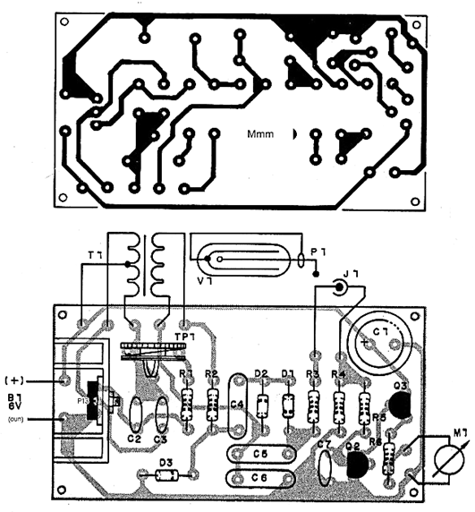
Almost all components are the same as the previous version, so the given specifications apply. Only instrument M1 appears as a new element. It is a microammeter salvaged from a VU meter from a sound system with a full-scale range between 100 and 250 uA. The original type was 200 uA, but others with similar sensitivity will work.
Resistant R6 can eventually be replaced by a 1 kΩ trimpot to facilitate full-scale adjustment. The R5/C7 network forms the integrated circuit, which can have its values changed depending on the scale. Thus, for R5 we suggest values between 100 kΩ and 470 kΩ, and in more critical work a 470 kΩ trimpot can be used in series with a 100 kΩ resistor, and for the capacitor values between 220 nF and 1 uF.
TESTING AND USE
For testing, it would be necessary to use a radiation source of known intensity to adjust the instrument's scale in more critical work. For less critical work, it is only necessary to observe if there is needle deflection when the sensor approaches a more intense radiation source. TP1 should be adjusted for optimal performance, at which point maximum alternating voltage is obtained across R2.
LIST OF MATERIALS
V1 - ZP1406 - Geiger-Müller tube (Philips)
Q1 - TIP31 - NPN power transistor
Q2 - BC548 - NPN transistor
Q3 - BC558 - PNP transistor
D1, DZ, D3 - 1N4007 or BY127 – rectifier diodes
B1 – 6 V - 4 medium or large batteries (preferably alkaline)
T1 - transformer with 110/220 V primary and 6 + 6 V secondary of 100 to 250 mA
S1 - simple switch
M1 - 0-200 uA microammeter (VU)
TP1 - 4k7 - trimpot
C1 – 1000 uF x 6 V - electrolytic capacitor
C2 – 47 nF - ceramic or polyester capacitor
C3 – 100 nF - ceramic or polyester capacitor
C4, C5, C6 - 150 to 470 nF x 600 V - polyester capacitors
C7 – 470 nF to 1uF - ceramic, polyester or electrolytic capacitor
R1 – 1 kΩ - resistor (brown, black, red)
R2 – 10 kΩ - resistor (brown, black, orange)
R3 – 47 kΩ - resistor (yellow, violet, orange)
R4 – 470 kΩ to 1.5 MΩ - resistor (choose the best value)
R5 – 100 kΩ - resistor (brown, black, yellow)
R6 - 1k2Ω - resistor (brown, red, red)
Miscellaneous: printed circuit board, mounting box, sensor material, shielded cable, holder for 4 medium or large batteries, wires, solder, etc.


