
Although it is a configuration already overcome, as we can have oscillators with more modern components, it is an interesting option for those who need a low frequency signal sawtooth with great amplitude. This type of circuit can be used to trigger SCRs, time bases of low frequencies and timing. The great advantage is in the ease of obtaining the components and in the simplicity of the circuit.
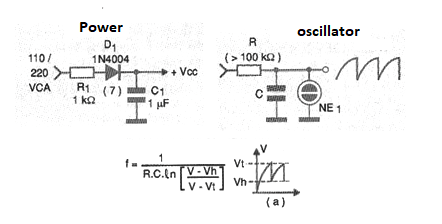
In figure 1 we have the basic configuration of this oscillator, indicated for the direct feeding through the power network. The power supply is given together.
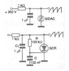
With this oscillator it is possible to generate signals in a range from hertz fractions (less than 0.001 Hz) to about 20 kHz or more, since the neon lamp is a slow device. The same configuration can be implemented with more modern devices such as diacs and sidacs and even SCRs, as shown in figure 2.
The formula that allows to calculate the operating frequency is given next to the diagram of figure 1 where V is the supply voltage, Vt is the tripping voltage typically of 80 to 90 V for the common lamps and Vh the maintenance voltage between 50 and 60 V for the same lamps.
The resistor R can have values between 100 k to 10 M ohms and the capacitor between 10 nF and 10 uF. For high values it is recommended to use depolarized capacitors (polyester).
Note in the graph that the voltage will oscillate between Vh and Vt when the oscillator is in operation.
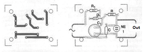
In figure 3 we have a suggestion of printed circuit board for implementation of this oscillator.
Material list
D1 - 1N4004 - rectifier diode (110 V) or 1N4007 (220 V)
NE-1 - common neon lamp (NE-2H or equivalent)
R1 - 1 k ohm x 5 W - wire resistor
C1 - 1 uF x 250 V (110 V) or 400 V (220 V) - capacitor
C - see text
R - see text
Several
Printed circuit board, wires, solder, etc.


