
The speed of a micromotor can be varied by changing the active cycle of the applied voltage. This technique, based on pulse width control, can be easily implemented with the use of the circuit shown in figure 1.
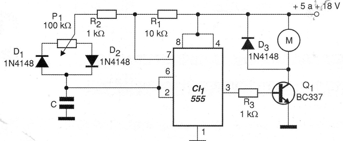
In the circuit presented the active cycle is determined by the change of the charge and discharge current of C through two diodes and the branches of a control potentiometer. The capacitor C can have values in the range of 100 pF to 100 nF depending on the characteristics of the motor to be controlled.
This capacitor will influence the operating frequency of the circuit which should not be that of the resonance of the motor. The circuit operates satisfactorily with voltages from 5 to 12 V and the maximum current of the motor depends on the transistor used.
With the indicated transistor, small motors of up to 500 mA can be controlled.
In figure 2 we have the printed circuit board for this assembly.
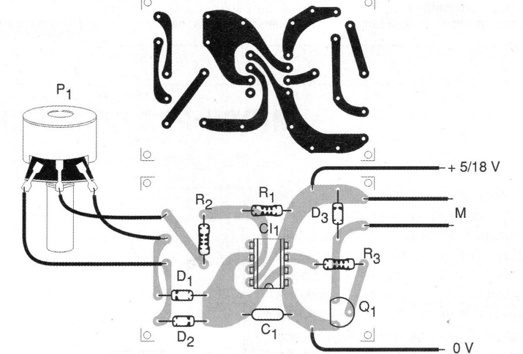
Depending on the power range to be applied to the motor the potentiometer may have its value increased to up to 1 M ohm. In fact, the assembler can play with the values of various components of the frequency network of the circuit in order to obtain the best performance with the motor used.
Material list
CI-1 - 555 - integrated circuit
Q1 - BC337 - medium power NPN transistor
D1, D2 - 1N4148 - general purpose diodes
R1 - 10 k ohm x 1/8 W - resistor - brown, black, orange
R2 - 1 k ohm x 1/8 W - resistor - brown, black, red
R3 - 1k ohm - brown, black, red
P1 - 100 k ohm - potentiometer
C - Capacitor from 100 pF to 100 nF - see text
More:
Printed circuit board, wires, solder, etc.


