
For readers that need high continuous voltages, a low current power supply can be built with few components. The source described provides up to 150 V in the 110 V network and up to 300 V in the 220 V network. The current, however, should not exceed a few tens of milliamperes.
Low-power valve transmitters and other similar circuits can be powered from this source. We note, however, that it is not isolated from the power grid, and that proper precautions must be taken against accidental shocks.
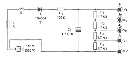
In figure 1 we have the complete diagram of the power supply.
In Figure 2 we have the arrangement of the components on a terminal strip.
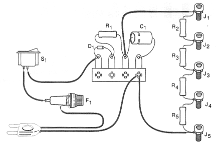
The diode should be 1N4004 if the grid is 110 V or 1N4007 if the grid is 220 V. The filter capacitor can have values between 4.7 uF and 50 uF with working voltages of at least 200 V if the grid is 110 V and at least 300 V if the grid is 220 V. The resistors of 4.7 k ohms must have dissipation of at least 2 W.
For the output we use insulated terminals. The assembly must be installed in an insulated box. Installing it in a tightly closed wooden or plastic box is important. To use, check with the multimeter the voltages obtained in each terminal, noting them, since they can vary appreciably according to the tolerances of the components.
If there is a marked voltage drop when connecting a circuit it is a sign that the current drained by this circuit is greater than that which the source can supply. In some cases, this problem can be compensated by connecting the equipment to a terminal that provides a higher voltage.
Do not touch any point of the source or the device when it is in operation, since the source is not isolated and may cause dangerous shocks. If you want to have insulation for extra safety you can use a transformer for this purpose.
Material list
D1 - 1N4004 or 1N4007 - silicon diode - see text
F1 - 1 A - fuse
S1 – On/Off switch
R1 - 100 ohm x 1 W - resistor (brown, black, brown)
R2 to R5 - 4.7 k ohm x 2 W - resistors (yellow, violet, red)
C1 - 4.7 uF at 50 uF - electrolytic capacitor according to mains voltage, see text
J1, to J5 - Isolated terminals
More:
Power cable, fuse holder, mounting box, wires, solder, etc.


