
This circuit serves to demonstrate the principle of operation of an LDR by driving an LED from the light that strikes this component. We can use it for technology demonstrations or classes, or for remote light sensing by connecting the LDR to the circuit by a long wire.
The circuit has its sensitivity controlled by a potentiometer and is powered by 4 small batteries. Any LDR can be used and the LED can be any color. In figure 1 we have the complete diagram of the device.
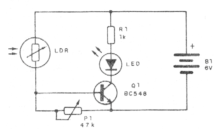
In figure 2 we have the assembly made using a terminal strrip. For technology classes, we suggest a protoboard mounting. The LED can be any color.
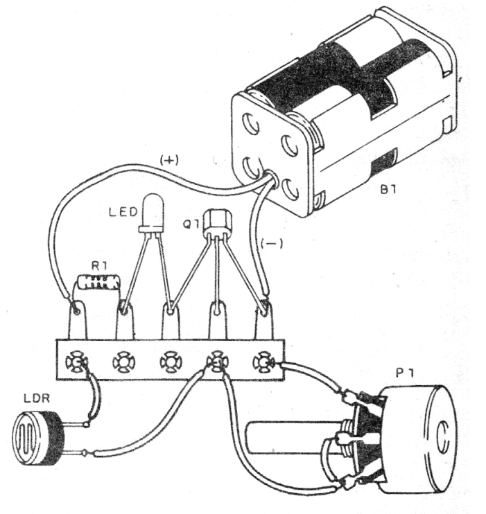
For testing and use, adjust the potentiometer so that when you put your hand in front of the shadowed LDR the LED goes out.
Material list
Q1 - BC548 or equivalent - General Purpose NPN Transistor
LDR - Common LDR of any kind
LED - Common LED of any color
P1 - 47k ohms - Potentiometer
R1- 1K ohms x 1/8 W - resistor - brown, black, red
Miscellaneous: battery holder, terminal bridge, wire, solder, etc.


