
In this type of oscillator an RC network is used to move the phase of the 180-degree feedback signal so that it can be applied to the inverting input and thus maintain the oscillations. The circuit shown in figure 1 uses an operational amplifier with field effect transistors and operates at about 1 kHz. The frequency is given in the formula next to the diagram itself.
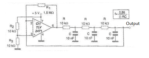
Note that thanks to the use of a reference network at the non-inverting input, which sets the voltage at this point in 2.5 V, it is not necessary to use a symmetrical source and the circuit can be supplied with only 5 V.
The signal generated is sinusoidal of good quality for other frequencies it is recommended to recalculate C, keeping R in 10 k ohm. A printed circuit board for mounting this oscillator is suggested in Figure 2.
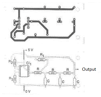
Note that the signal can also be removed from the output of the operational, but the load to be used must be observed so that it does not load the circuit, preventing the oscillations or deforming the signal.
Material list
CI-1 - TLV2471 or other operational amplifier with FET at the input
R - 10 k ohm x 1/8 W - resistors
C-10 nF - capacitors
R1 - 1.5 M ohm x 1/8 W - resistor
R2, R3 - 10 k ohm x 1/8 W - resistors
More:
Printed circuit board, single power supply, wires, solder, etc.


