
The circuit shown in figure 1 is a fast solution for controlling an external load through relay from signals obtained from the parallel port of a PC. It also be used as a power shield for microcontrollers
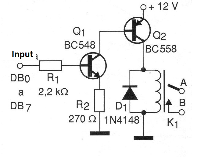
We can use this circuit as part of a control interface, in tests of automated equipment by a software or even to test equipment that must be controlled by a computer. The recommended relay is of the sensitive type with 50 mA coil current and contact current according to the load to be controlled. The voltage of the relay depends on the external power for this sector of the circuit.
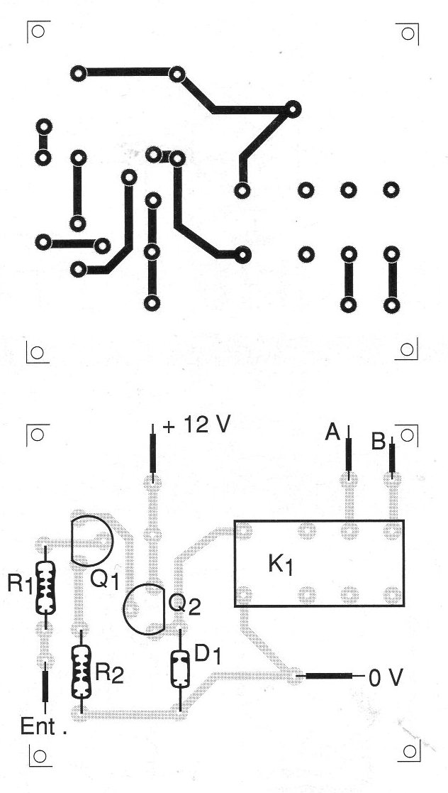
We show only one control channel, but a complete interface can be elaborated with the use of 8 circuits like this one. In figure 2 we have a suggestion of printed circuit board in which the used relay has DIL enclosure. For other types of relays the design of the board must be modified.
The connection to the computer must be made through a DB-25 connector on the outputs of DB0 to DB7, according to the control line that will be used in the application.
LIST OF MATERIALS
Q1 - BC548 - NPN general purpose transistor
Q2 - BC558 - general purpose PNP transistor
D1 - 1N4148 or equivalent - silicon diode
R1 - 2.2k ohm x 1/8 W - resistor - red, red, red
R2 - 270 ohm x 1/8 W - resistor - red, violet, brown
K1 - Sensitive 12 V relay - see text
More:
Printed circuit board, connection terminals for the load, DB-25 connector, wires, solder, etc.


