
With this simple circuit we can light 4 to 20 W fluorescent lamps using four large cells or a 12 V battery. We can also use alternative sources formed by solar cells, dynamos or others, provided they provide a minimum current of the order of 500 mA .
Even fluorescent lamps that no longer light on the 110V or 220V network, because they are weak, can be used in this circuit. However, given the circuit performance the brightness will be lower than in normal application.
The circuit consists of an oscillator that operates around 1 kHz and since the output is not sinusoidal, peaks larger than 200 V can occur, which easily ionize the gas even from low light bulbs. In figure 1 we have the complete inverter circuit.
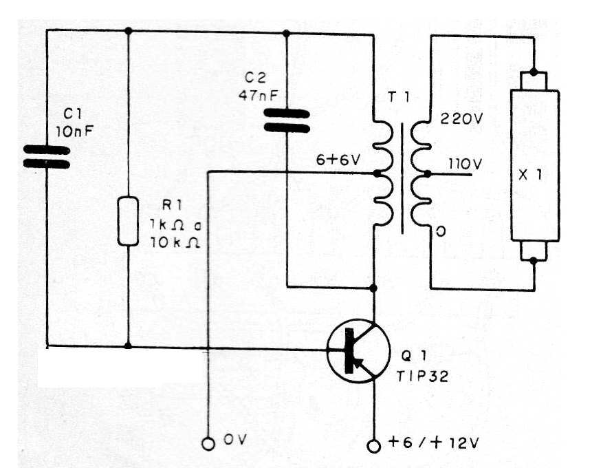
The transformer is of the type found on small primary power supplies according to the local and secondary 5 to 9 V mains with 300 to 500 mA current. The transistor shall be equipped with a heat radiator. In figure 2 we have the assembly based on a terminal strip.
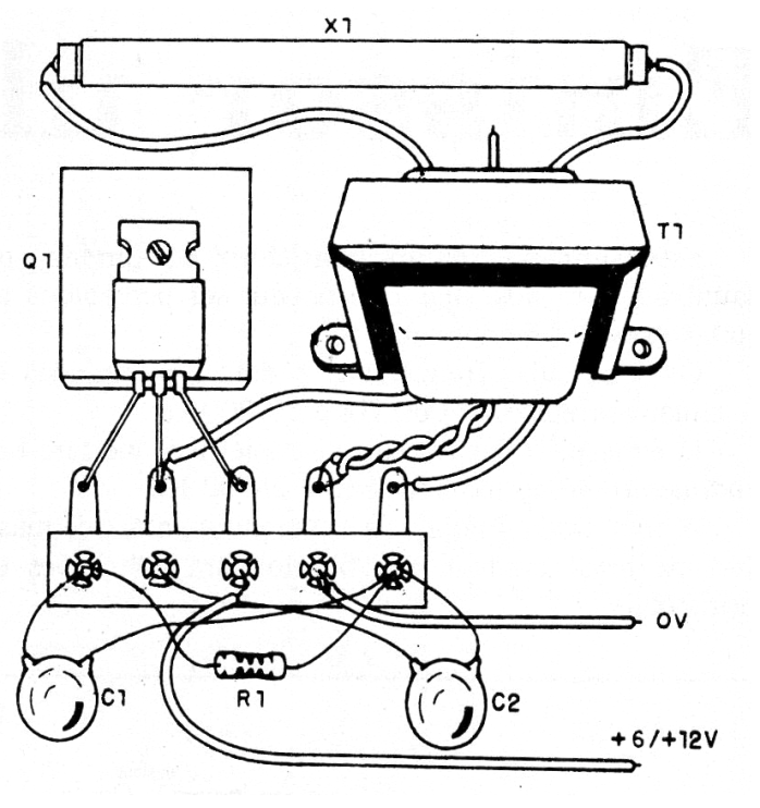
Capacitor C2 should eventually be changed for best performance. In series with R1 we can connect a 10k potentiometer (using R1 = 1k) and thus adjust the circuit for the best performance, depending on the transformer and the lamp.
Material list
Q1- TIP32 - PNP Power Transistor
X1- 4 to 20 W - fluorescent lamp
R1- 1k ohm to 10k ohms x 1/8 W - resistor - see text
C1 - 10 nF - Ceramic or Polyester Capacitor
C2 - 47 nF - Ceramic or Polyester Capacitor
T1- Transformer - see text
Miscellaneous: terminal bridge, wires, battery or batteries with power support, transistor heat radiator, welding, etc.


