
This source only uses passive components (no transistors or integrated circuit) and yet it can provide well-regulated voltages in 0.7 V steps and an output current of up to 200 mA.
There are 5 voltages indicated in the diagram and can be used up to the same time, if the appliances supplied do not require more than the indicated current.
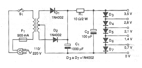
The circuit consists of a rectifier, filter and then a reduction system that takes advantage of the voltage drop in the direct direction of a diode in conduction. This voltage varies between 0.6 and 0.7 V per diode, which allows staggering the indicated voltage range with a tolerance between 10% and 20% typically.
Filtering is good which makes it possible to power small devices that normally use one or two batteries. In figure 1 we have the complete diagram of the proposed supply.
The assembly of the source based on a terminal strip is shown in figure 2.
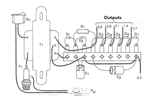
The transformer has primary winding according to the power grid, ie 110 V or 220 V. The secondary is 6 + 6 V with currents of 200 mA at 500 mA, The capacitor C1 must have a working voltage of 12 V or more and the resistor R1 must be of wire with at least 2 W dissipation. The diodes are 1N4002 or equivalent.
For the output it is at the discretion of the reader to choose the mode of connection to the external circuits. One outlet is the use of terminals with the voltages identified, where wired plugs and alligator clips would be connected.
The common goes to the black and red terminal to the terminal with the desired voltage. Another possibility for assembly is to use a selector switch.
To use, simply choose the desired output and the zero volt point that will be used when connecting to the external circuit. Before using the power supply, if you want good indication accuracy, check with the meter the actual voltage being obtained at each output.
If the voltage drops too high when powering an appliance, it means that it is requiring a current greater than the power supply can supply.
Material list
D1 to D7 - 1N4002 - rectifier diodes
R1 - 10 ohm x 1 W - wire resistor
C1 - 1000 uF x 12 V - electrolytic capacitor
C2 - 100 uF x 12 V - electrolytic capacitor
T1 - Transformer with primary according to the local and secondary network of 6 + 6 V x 200 to 500 mA
F1 - 500 mA Fuse
S1 – On/Off switch
More:
Terminal bridge, power cable, mounting box, fuse holder, wires, solder, output terminals, etc.


