
This simple circuit uses an LDR as a sensor to measure light intensity in a given environment. The circuit has no linear scale, so it is not for accurate measurements, but only for demonstrations.
We can use it to explain the principle of how LDRs work in technology classes, electronics, or optics experiments in the physics lab. In figure 1 we have the complete diagram of the photometer.
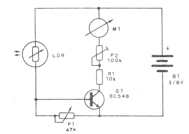
P1 adjusts sensitivity while P2, which can also be a trimpot, serves to adjust the instrument's full scale. M1 may be a 50 to 200 µA full scale microammeter or even a 1 mA full scale milliammeter. The circuit runs on 2 or 4 small batteries and has a very low power consumption.
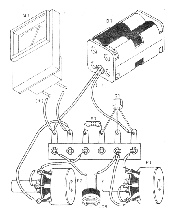
Material list
Q1 - BC548 - General Purpose NPN Transistor
LDR - Common LDR of any kind
M1 - Analog indicator instrument - see text
P1 - 47k - Potentiometer
P2 - 100k ohms - trimpot or potentiometer
R1- 10K ohms x 1/8 W- resistor - brown, black, orange
B1-3 or 6V - 2 or 4 small batteries
Miscellaneous: terminal bridge, battery holder, wire, solder, etc.


