
Oscillators over the Wien Bridge produce sinusoidal signals of low frequencies of excellent quality. However, one of the difficulties that the implementation of this type of circuit in its traditional form is the need to use a voltage regulator in the feedback circuit.
In traditional types the non-linear characteristic of an incandescent lamp is used for this purpose. However, both the consumption and the difficulty of finding a lamp with the ideal characteristics limit the applications of this configuration. In the more modern circuits this regulation can be done through zener diodes, and this is exactly what we do in the circuit shown in figure 1.
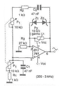
The circuit in question can generate signals of approximately 300 to 3 kHz (depending on the tolerances of the components used) and is based on a common operational amplifier. The zeners used are 5.6 V, but lower voltage zeners can be used in configurations that use amplifiers that can also be fed by lower voltages.
The potentiometer controlling the frequency must be linear double, as shown in the diagram. The range of frequencies generated depends on both C1 and C2, which must be equal and can be changed over a wide range of values, depending on the intended applications. In figure 2 we have a suggestion of printed circuit board for the implementation of this oscillator.
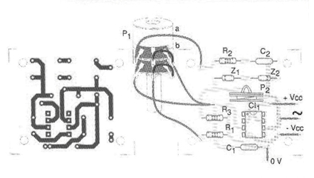
For the 741 operational amplifier the power supply must be symmetrical from 6 to 12 V. In the P1 trimpot the gain of the circuit is adjusted so as to obtain the signal with the greatest amplitude possible without distortion.
Material list
CI-1 - 741 or equivalent - operational amplifier
Z1, Z2 - Zener diodes of 4.7 or 5.6 V - 400 mW
P1 - 10 k ohm - double potentiometer
P2 - 10 k ohm - trimpot
R1, R2 - 1k ohm x 1/8 W - resistors
R3 - 27 k ohm x 1/8 W - resistor
C1, C2-47 nF- ceramic or polyester capacitors
More:
Printed circuit board, symmetrical power supply, button for potentiometer, wires, solder, etc.


