Obs. This article is part of one of my books published in USA.
Features
Frequency range: 3 to 7 MHZ (40 to 80 m band)
Output power: 2 to 5 W
Power supply Voltage: 117/220/240 Vac
Produced signal: CW
If you’re looking for a CW transmitter to test your skill in telegraphy or to learn Morse code this is an interesting project. As mentioned, this transmitter, if used by an amateur radio operator and equipped with an appropriate antenna, can send signals over great distances.
But the principal advantage to readers who want to conduct radio transmission experiments is that this transmitter can be built using parts found in old radio and television sets.
The tubes are common in 1960s/ 1970s vintage TVs and radios and can be cannibalized from abandoned units. As this circuit is intended for the reader who wants projects for experimentation and education, it bears repeating that it should not be used with large or external antennas.
See about the laws and rules of telecommunications.
How It Works
This SW transmitter can be operated in two configurations:
It can be used as a CW (continuous wave) unit, where the transmitted signals consist of high-frequency pulses produced by a key.
It also can serve as an AM (amplitude modulated) tone telegraphic transmitter. In this mode, the high-frequency signal is modulated by keyed pulses of a tone produced by an oscillator.
Figure 1 shows the wave shape of a CW signal when transmitting the letter R and also a tone-modulated signal transmitting the same letter (- - -) in Morse code. The reader is free to choose either version.
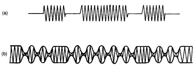
In our transmitter, if the AM version is chosen, the modulation tone is produced by a relaxation oscillator using a neon lamp. In this circuit, the frequency depends on the resistor and the capacitor (RC).
When the circuit is powered on, the capacitor charges until the trigger voltage of the neon lamp is reached. When the neon lamp triggers on, the capacitor discharges through it, producing a current pulse. When the capacitor is discharged, the neon lamp turns off, and a new charging cycle begins.
The high-frequency signal (RF) to be transmitted, and which serves as the carrier for the tone signal, is produced by a Hartley oscillator using a pentode tube.
Any audio or video pentode can be used in this circuit such as the 6L6, 6V6, 6AQ5, etc. These tubes are designed for use in audio power output amplifiers but, because they have a high cutoff frequency, they can also can be used to produce high-power radio signals.
Many radio amateurs have built their own transmitters using these tubes. This configuration was very popular in the 1960s/1970s. Tube sockets can also be found in the same equipment from which you extract the tube.
Figure 2 shows the pinout of some tubes that can be used for this transmitter. Coil L1 and CV determine the frequency produced.
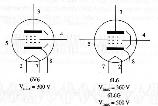
CV is any variable capacitor as found in old radio sets. The use of small, plastic variable capacitors is not recommended, as they can’t isolate the high voltage found in this circuit.
The output power for this circuit depends on the voltage applied to the tube.
This voltage depends on the power transformer employed. The reader can find a good transformer, suitable for this project, in many old tube TV sets and radios. The transformer must be a type with a high-voltage secondary rated to voltages between 125 and 300 V.
The transformer also must have a low-voltage secondary rated to 6.3 V, which is the voltage necessary to heat the tube (filament). If the voltage applied to the tube is higher than the recommended limit, the tube can be burned out within a few moments, and the transmitter will not operate as desired.
Observe that the voltages used for this circuit are very high, which means that there is a shock hazard. Although the circuit is isolated from the ac power line by the transformer, you should exercise much care when working on it while the power is on.
It is also important to use a variable capacitor that has a wide gap between the plates. If the gap is narrow, sparks can be produced, degrading the transmitter’s operation.
The electrolytic capacitors used to filter the dc current must be rated to a voltage at least 80% higher than the secondary winding high voltage. For a 125 V secondary winding, for instance, you should use 200 WVDC electrolytic capacitors.
In old tube-based equipment, diode tubes were used to convert the ac to dc. As we can find semiconductor diodes that offer a very low price as compared to the cost of tubes, this option was chosen for our project. The diodes recommended for all versions are the 1N4007 components.
For the antenna, you can use a piece of plastic-covered wire 3 to 10 ft long.
Don’t use longer antennas or external antennas, as the signal produced will be strong enough to create legal problems for you. If an external antenna is used, the signal can be picked up from the circuit by a coil of 4 or 5 turns wound over L1.
Assembly
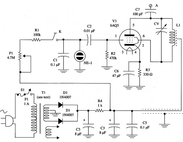
The complete diagram of the shortwave tube transmitter is shown in Fig. 3.
The circuit is mounted using a metallic chassis as shown in Fig. 4.
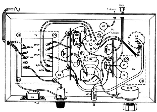
Locate the principal parts such as the transformer and C3/C4 before working on the chassis. These components exist in several shapes and dimensions, and the reader should design his own chassis to match the components that are on hand.
If it is difficult to find an appropriate chassis, the reader can use a metal plate by cutting, bending, and drilling holes in it. Observe that the use of a metal chassis is important, as it acts as an electromagnetic shield to prevent hum.
L1 is formed by winding 15 + 15 to 20 + 20 turns of AWG 26 to 28 enameled wire on a 1 in. PVC tube. With a coil of 20 + 20 turns, it is possible for operation between 3 and 7 MHz. With a coil of 15 + 15 turns, the frequency range will be between 5 and 10 MHz.
Note that these values are not exact, as there are component tolerances involved as well as variations in the variable capacitor. The variable capacitor, for instance, can be any type with capacitances in the range between 120 and 410 pF.
Remember that the capacitor must be mounted on an insulator so it does not touch the chassis.
Figure 5 shows how the transmitter looks after assembly.
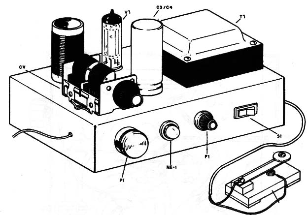
Figure 6 shows how the Morse key is connected to the circuit for CW transmission.
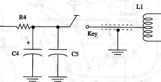
Take care when using the Morse key, as it is exposed to high voltages when the transmitter is on.
C3, C4, and C5 must be ceramic capacitors rated for high voltages; 400 V is a suitable value. Cl and C2 can be metal film types with working voltages of 100 V or more.
Testing and Using the Circuit
To test the circuit, place it near an SW receiver that has been tuned to a free point in the band. Power the transmitter on with 81 and wait two or three minutes for it to warm up.
The tube will emit a weak red light when hot. Pressing the Morse key, tune the variable capacitor until the signal is received.
Adjust P1 to obtain the desired tone for modulation.
The output power can be verified using a Hertz loop as shown in Fig. 7.
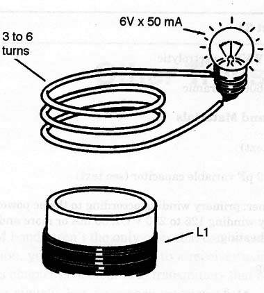
The stronger the output power, the brighter the lamp glows. Alternatively, a fluorescent lamp will glow from the high-frequency signals if it is placed near the coil or touching the antenna terminal.
If no signal is produced, check to see if there is high voltage in the tube plate (V2). If there is voltage but no oscillation, the tube is burned out and cannot be used.
If there is no voltage in the power supply output, verify the operation of the transformer and the electrolytic capacitors.
If the lamp lights up but the signal isn’t picked up by the receiver, change the coil or try to find the signal in another part of the frequency band.
Tube
V1 - 6AQ5 or equivalent miniature pentode (see text) to equivalents
Semiconductors
D1, D2 1N4007 or equivalent silicon rectifier diode
Resistors (1/8 W, 5%)
R1 - 100,000 ohm -brown, black, yellow
R2 - 470,000 ohm -yellow, violet, yellow
R3 - 330 ohm -orange, orange, brown
R4 - 1,000 ohm X 5 W wirewound
P1 - 4,700,000 ohm - potentiometer
Capacitors
C1 - 0.1 µF/ 100 V ceramic or metal film
C2 - 0.01 µF/200 V ceramic or metal film
C13, C4 - 8 µF to 32 µF/450 V or more, electrolytic (double) (see text)
C5 - 0.1 µF/600 V ceramic
C6 - 47 µF/25 WVDC electrolytic
C7 -100 pF X 600 V ceramic
Additional Parts and Materials
L1 - coil (see text)
CV - 210 to 410 pF variable capacitor (see text)
T1 - transformer: primary winding according to the ac power line voltage, secondary winding 125 to 250 V CT, 80 mA or more and 6.3 V x 1 A for filament heating
NE - neon lamp
F1 - 1 A fuse and holder
S1 - SPST toggle or slide switch
Metal chassis, wire for the coil, power cord, knobs for the variable capacitor and
potentiometer, Morse key, socket for the tube, etc.


