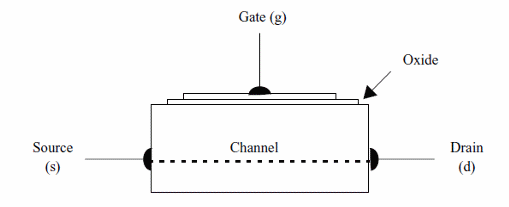
As shown by the strucuture in figure 1, the MOSFET have a thin layer of metal oxide (silicon oxide) isolating the substract from the gate region, instead a junction found in the J-FET.

But, altough the differences in the structure the operation of a MOSFET is
the same: a voltage applied in the gate can control the amount of current accross the device or the current between drain and source.
The layer that isolates the gate region from the channel is very thin making the device extremelly sensitive to static discharges. If you have a static charge in your body, any touch in any terminal of the device a spark between gate and the channel can be produced destroying the isolating layer and so the device.
Figure 2 shows the symbols of the two types of MOSFETs commonly found in electronic circuits. This figure also shows the aspects of these devices.

As we can see by this figure the MOSFET can also be found in a two-gate version (g1 and g2). The amount of current accross the device can be controlled independently by the voltages applied to each of the two gates. This device, in special, is suitable for applications where two signals must be mixed.
The common MOSFETs are low power devices and by their aspects the electrician can't differenciate it from bipolar transistors. It is necessary to have the schematic diagram, a data sheet with informations or the type (part number figured in its package).
Power FETs are MOSFETs that can be used to control large amounts of current. They are very common today in digital and analog applications replacing the bipolar transistor in many cases with advantages. Power FETs or Power-MOSFETs are they also called, can control currents as large as 50 amperes under voltages of more than 500 volts.
The structure and the operation principle of a power MOSFET is the same of the common MOSFET. The differences are in the size and shape of the silicon chip used when the device is manufactured.
Several technologies are used to produced these devices giving to the POWER-MOSFET transistor names as V-FETs, Power-FETs, D-FETs, TMOS, etc.
The power FETs operate the same way the common MOSFET. A voltage applied to the gate can controll the amount of current flowing accross the device.
High current devices as solenoids, motors, electromagnets, relays, heaters, lamps, can be controlled by power FETs in the same kind of stages as the ones who use Power Bipolar Transistors or Darlington Transistors.
The main advantage found in the use of Power-MOSFETs is the low resistance it presents when conducing a current (named Rds or drain source resistance). As the amount of heat produced by the device depends on this resistance, Power-FETs can control much larger currents than the equivalent bipolar transistor, generating less heat.
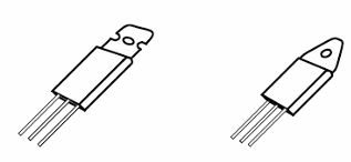
Figure 3 shows that the Power FETs can be found in two types N and P-channel. The aspect is the same of power bipolar transistor as they use the same packages.

N-Channel MOSFETs conduces the main current when a positive voltage is applied to the gate and P-Channel MOSFETs conduces when a negative voltage is applied to the gate.
As any other power transistor, the Power MOSFETs must be mounted in heatsinks to transfer to the ambient all the heat they generate when working.
Specifications
The Power MOSFETs are identificated by a part number. A popular series of Power MOSFETs and produced by many manufacturers as International Rectifier, Fairchild, Motorola, etc is the "IRF" series. All devices of this series have names beginning by "IRF" taking as example the IRF640, IR720, IRF630, IRF730, etc.
By the name (part number) it is possible to find the electrical characteristics of a Power MOSFET in handbooks, Internet or data sheets. The principal characteristics are:
a) Maximum voltage between drain and source
Is the maximum voltage that can be applied to the device without burn it. Common types have voltages ranging from 50 to 1,000 volts. This specification can be indicated as Vds(max).
b) Maximum drain current
Is the higher current that can be controlled by the device. It is also abreviated by Id and can range from 1 to 50 amperes. This specification is also abreviated by Id or Id(max).
c) Dissipation power
Indicates the amount of heat that the device can transfer to the ambient. It is measured in watts and can range from 10 to 250 watts.
d) Resistance between drain and source in the on state
This is one of the most important of the Power-FETs specifications. The amount of heat generated by the device depends on this resistance as it operates in more of the applications as electrolic switches. The product this resistance by the square of the current gives the generated power. It is easy to see that as low is this resisistance more eficient is the device when controlling high amounts of current and more heat is generated. This resistance uses to be less than 1 ohm in more of the common devices and is also idicated by rDS or Rds and is given in Ω (Ω).
How to Use
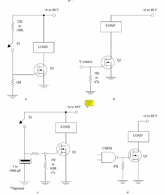
Power MOSFETs are used replacing common bipolar transistor in the control of high current loads. Figure 4 shows some circuits using Power MOSFETs.

a) On-Off Switch - for low current switches
b) Control stage
c) Timer
d) Driven by CMOS logic
Since Power MOSFET are very high input impedance devices they need almost no power to be driven. The voltage to turn on a MOSFET is between 1 and 2 V typically.
How to Test
The simplest test is the measure of the resistances between drain and source that may be high and between gate and source or gate and drain that may be very high too.
Obs: some Power MOSFETs have a diode between drain and source, so when measuring the resistance between those terminals, in one direction it will be high and in the opposite will be low.
Popular Power MOSFETs - Table
| Vds | Rds(on) | Ip | |
| IRF120/IRF520 | 100 V | 0.3 ohm | 8.0 A |
| IRF121/IRF521 | 60 V | 0.3 ohm | 8.0 A |
| IRF122/IRF522 | 100 V | 0.4 ohm | 7.0 A |
| IRF123/IRF523 | 60 V | 0.4 ohm | 7.0 A |
| IRF140/IRF540 | 100 V | 0.085 ohm | 27 A |
| IRF141/IRF541 | 60 V | 0.085 ohm | 27 A |
| ITF142/IRF542 | 100 V | 0.11 ohm | 24 A |
| IRF143/IRF543 | 60 V | 0.11 ohm | 24 A |
| IRF230/IRF630 | 200 V | 0.4 ohm | 9.0 A |
| IRF231/IRF631 | 150 V | 0.4 ohm | 9.0 A |
| IRF232/IRF632 | 200 V | 0.6 ohm | 8.0 A |
| IRF233/IRF633 | 150 V | 0.6 ohm | 8.0 A |
| IRF240/IRF640 | 200 V | 0.18 ohm | 18 A |
| IRF241/IRF641 | 150 V | 0.18 ohm | 18 A |
| IRF242/IRF642 | 200 V | 0.22 ohm | 16 A |
| IRF243/IRF643 | 150 V | 0.22 ohm | 16 A |


