
ART1570S ART2401
Note: The article is from 1987, there are more modern reading processes and even the two-dimensional code, but it is valuable for its didactic approach.
The basic idea of barcode coding is to use optical sensors to read information. Since the devices to which we connect these sensors operate digitally, that is, they work with base 2, where the presence of information means a "1" and its absence a "0", nothing is better than adapting this to optics: the color black represents one signal level (0 or LO) and white another level (1 or HI).
Note that we do not fix which one it will be or the other, as variations exist and they will become clear as we give our applications. In fact, there is a large number of codes that make use of bars, and the "interpretation" of each one must be analyzed separately, as we will do from now on. (figure 1)
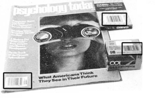
The Simplest Code
Certainly, the simplest code we can imagine simply dictates that a black bar means 1 and a white bar or "space" means 0, as shown in Figure 2.
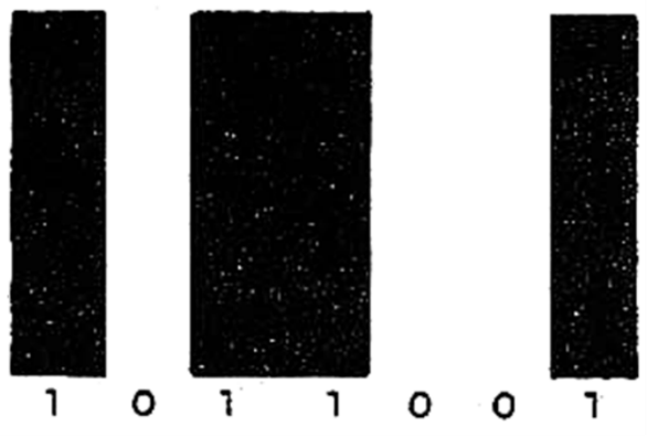
Under these conditions, the bars and spaces will have the same width, but the system has serious drawbacks. One of them is the "code length".
If we make a numbering in pure binary, such as the number 7,895, this would result in a huge recording, as shown in Figure 3.
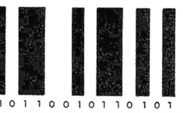
The other drawback comes from the fact that the reading system does not know exactly where the number begins, especially if it has many zeros to the left.
The "2 of 5" Code
A considerable improvement in writing and reading what is intended to be placed on products is obtained, in a first step, with the code called 2 of 5.
In this code, as it is called, two wide bars and three narrow bars in black are always used. (Figure 4)
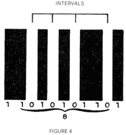
Note from the figure that the intervals between the bars have a constant width. Since the number of combinations we can obtain with the 5 bars is limited, this code only serves to represent digits and some symbols, according to the following table:
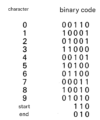
Note, then, that the wide bar is represented by 1 and the narrow bar by 0. An important characteristic of this system is the recognition of the beginning and end of the number by means of its own symbols. With this, the reading system can be used in either direction. The circuit "records" the message and if the circuit detects that it is reversed, the reversal is done automatically. The product can then enter the reading machine in any way! (Figure 5)
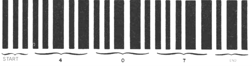
The consistency of the bar number for each digit also serves as a verification element. The device used for reading can "count" the bars, and if we have a total that is not a multiple of 5 (without the beginning and end or outside of 6), it means there is an error that can be detected! This code has some interesting variations, such as the so-called "industrial" code.
Industrial 2 of 5 Code
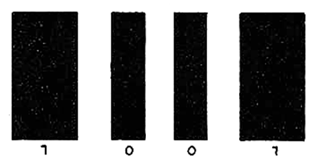
In this system, wide and narrow black bands are used, each with a "discrete" meaning. Thus, 0 is represented by the narrow band and 1 by the wide band. The white bands, always the same width, are used only for spacing. (Figure 6)
Matrix 2 of 5 Code
This code, more interesting, differs from the previous one by using the colors black and white, both to represent digits and intervals, and also taking into account their width. Thus, in Figure 7 we have an example of what occurs.
What we have is an alternation of black and white where the smaller width (regardless of color) means a 0 and the larger width (regardless of color) indicates a 1. (figure 7)
In short, the color serves to indicate that a new digit is appearing, while the width indicates this digit! See then that we obtain a considerable reduction in the size of the information, since we no longer need the intervals! In fact, the intervals only appear in the separation of the digits, since each one must always start with a black bar. (figure 8)
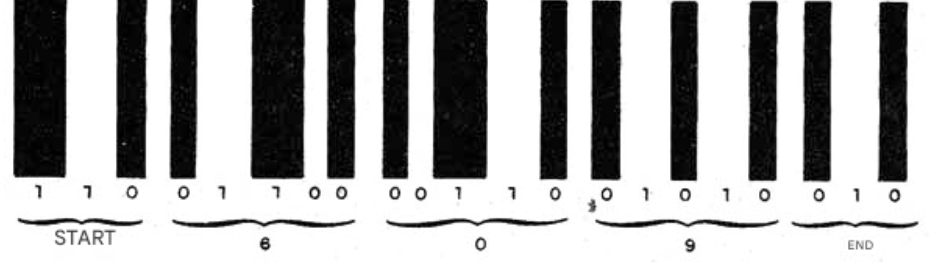
Intertwined code 2 of 5
As shown in Figure 9, we have a rather ingenious arrangement of the bars in this case.
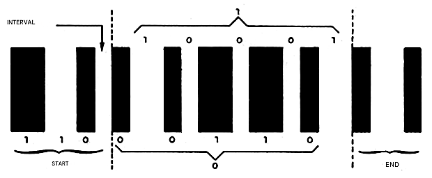
What happens is that one digit is represented by the black bars while the other digit, which follows it, is represented by the white bars or intervals. Thus, we have a reading order by the sensor in a "zigzag" pattern as shown in Figure 10.
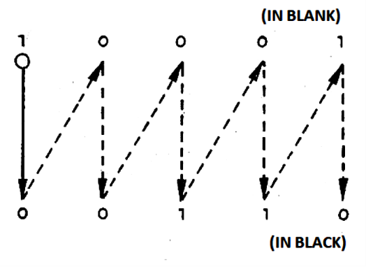
One digit is then "interleaved in another," hence the code's name.
The UPC Code
The acronym UPC stands for Universal Product Code; it is a simple solution for product marking. With this encoding, we represent the digits from 0 to 9 plus the beginning or end, according to the following table:
| Character | code |
| 0 | 3-2-1-1 or 1-1-2-3 |
| 1 | 2-2-2-1 or 1-2-2-2 |
| 2 | 2-1-2-2 or 2-2-1-2 |
| 3 | 1-4-1-1 or 1-1-4-1 |
| 4 | 1-1-3-2 or 2-3-1-1 |
| 5 | 1-2-3-1 or 1-3-2-1 |
| 6 | 1-1-1-4 or 4-1-1-1 |
| 7 | 1-3-1-2 or 2-1-3-1 |
| 8 | 1-2-1-3 or 3-1-2-1 |
| 9 | 3-1-1-2 or g-1-1-3 |
| start/end | 1-1-1 |
Note that this code can be read both from "beginning to end" and from "end to beginning," which is interesting since you do not have to worry about the "way" the product enters the reading system. The digits 1, 2, 3, and 4 correspond to the relationships between the widths of the lines. Thus, to represent the digit 5 we have:
- A bar (black or white) of unit width;
- A bar (black or white) of width equivalent to two units;
- A bar (black or white) of width equivalent to three units;
- A bar (black or white) of unit width.
The start/end symbol, with two dark bars and one light bar of unit width, also has another use besides showing where the number begins: it serves to indicate to the reading system the unit width of the bars, since all the others are made in reference to it. '
Code 3 of 9
In this code, each symbol has 9 elementary signs (dashes or spaces), thus allowing the representation of both numbers and letters, as shown in the following table:
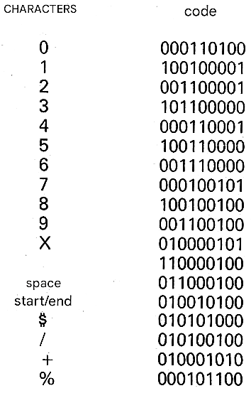
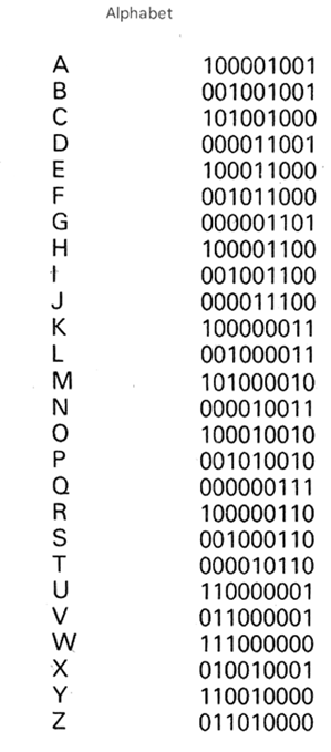
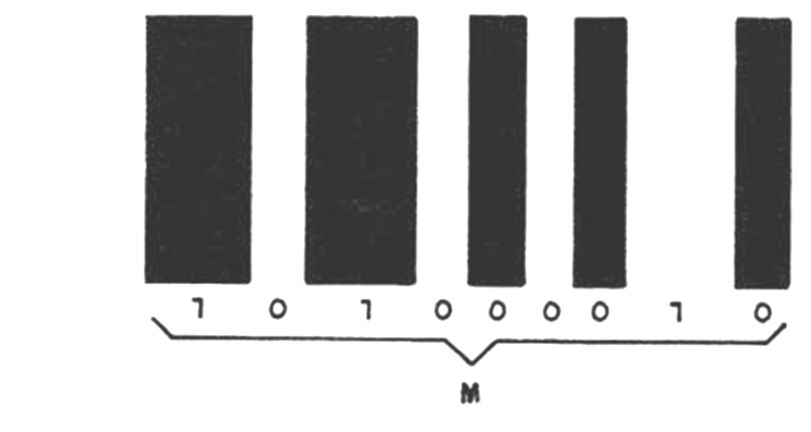
In this code, 0 is represented by a thin line (light or dark) and 1 by a thick line (light or dark).
Figure 11 shows an example of how this code, which is the most commonly used, is applied.
The HP Code
Hewlett-Packard, the manufacturer of scientific calculators such as the well-known HP-4.1C, offers an interesting example of barcode application in the availability of optical accessories. Using an "optical pen," various types of data can be entered into the HP-4.1C calculator via appropriate peripherals, as shown in Figure 12.
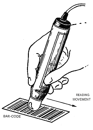
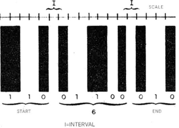
Note: Today, cell phones and tablets perform this reading using the video camera. In the code used by HP, dark lines of two widths are employed. The narrower one indicates 0 and the wider one, 1, with a uniform separation for both. The reading is done in the form of a succession of octets, that is, groups of eight digits, as shown in Figure 13.
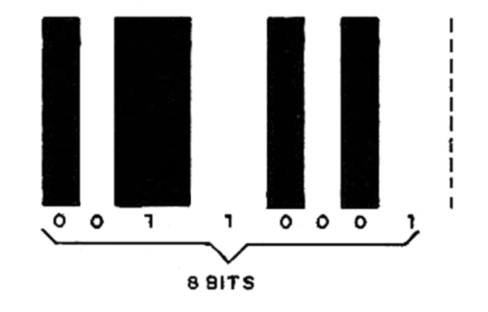
Note in the figure the existence of start and end reading symbols, as in the other codes analyzed.
Reading the codes
Several techniques are employed in reading. In all of them, it is necessary to take into account what is intended to be differentiated in order to gather the correct information. Thus, we have both cases where it is only necessary to differentiate light from dark, and cases where, in addition, the system has to discriminate the width of the light or dark areas. Figure 14 shows a typical reading system circuit that provides digital information at its output, ready to be processed by a processing circuit.
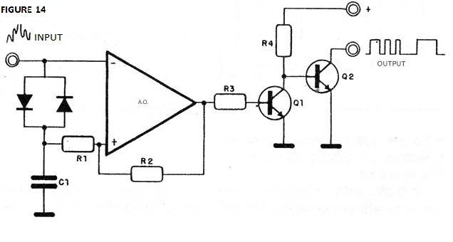
The use of lenses, or the concentration of light in a specific way, is sometimes very important in facilitating reading. The sensor, as we have already explained, can be a sensitive phototransistor.
Conclusion
When visiting the supermarket and noticing the existence of barcodes on products, the reader should not be surprised. Consider that, perhaps in the very near future, all products will be controlled by machines, and these will only be able to read symbols that are favorable to them. The barcodes are the alphabet that optical readers can understand, and since computing is already an integral part of our lives, we have to get used to it.
Note: Remember that this was written in 1987.


