
ART1756S ART2404
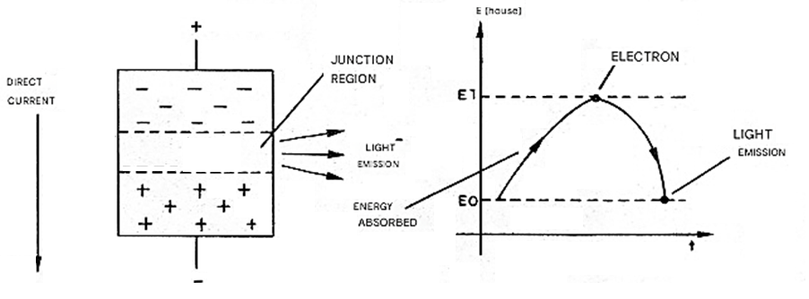
When a current flows forward through the junction of a light-emitting diode (LED), light is emitted. Its color or frequency depends on the nature of the material used in the junction. We then have red, yellow, and green LEDs, which are the most common, in addition to the recent blue, violet, and other LEDs. The emission of light is due to the excitation of electrons that jump to higher energy levels and, on the return, release the absorbed energy in the form of a photon with a well-defined wavelength. (Figure 1)
What many readers may not know is that in addition to emitting light, common LEDs are also sensitive sensors of this type of radiation and can even be used in important applications. What we propose in this article is precisely an experimental circuit that uses a common LED, not as a light emitter, but as a photo sensor controlling the frequency of an audio oscillator. The circuit is powered by a 3V voltage and is also quite simple to assemble, ideal for school projects or demonstrations.
How it Works
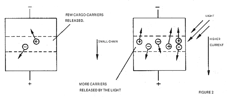
The inverse effect to the natural effect in an LED is sensitivity to light. This sensitivity can be explained as follows: when light falls on the semiconductor junction of an LED, charge carriers are released, which means a change in reverse resistance.
Thus, like a common diode, LEDs have a very high reverse resistance, which depends on the amount of charge carriers that are released, whether by natural thermal agitation (heat) or by the incidence of light. If we shine light onto an LED at a wavelength capable of releasing charge carriers, its reverse resistance undergoes considerable changes that can be used to control a circuit (Figure 2).
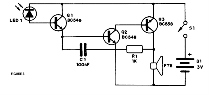
The circuit we use in our case is an audio oscillator.
Its frequency depends not only on capacitor C1, but also on the resistance presented by transistor Q1. This transistor serves precisely to amplify the weak current that flows through the LED when light falls on it, and its resistance decreases. This means that when the LED receives light, the resistance of Q1 decreases, thus increasing the frequency of the signal produced by the audio oscillator.
In the experiments we conducted, we noticed that the LEDs most sensitive to natural light are yellow and green. Red LEDs can also be used, but will have lower sensitivity. Another possibility is to connect two or more LEDs in parallel.
Assembly
Figure 3 shows the complete circuit of this experimental setup using transistors.
Its practical implementation on a terminal strip is shown in Figure 4.
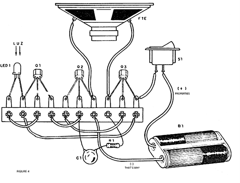
The transistors are general purpose, and the speaker is small (5 or 10 cm) with 8 ohms. The single resistor can be 1/8, 1/4 or even ½ W and the capacitor C1, ceramic or polyester, can have its value changed over a wide range. Depending on the tone of the sound produced under various lighting conditions, values between 33 nF and 1,000 nF (1uF) can be experimented with without problems, including larger electrolytic capacitors.
The assembly can be installed in a small box, with the LED mounted in an opaque tube so as to receive light only from one direction. As a light source for excitation, a lampshade, a candle, or even ambient lighting can be used.
Testing and Use
Activating S1 and letting light fall on the LED should result in the immediate emission of sound. With the LED in the dark, the sound should stop or, at most, a rhythmic pulse should occur. If there is no remote control, check if the LED is not connected backwards. An interesting experiment involves using a flashlight as a "remote control". Focusing the light beam on the LDR will trigger the oscillator.
Material List
Q1, Q2 - BC548 - NPN transistor or equivalent
Q3 - BC558 - PNP transistor or equivalent
LED1 - Common green or yellow LED
B1 – 3V - 2 small batteries
S1 - Simple switch
FTE - Small 8-ohm speaker
C1 - 100nF (104) - Ceramic or polyester capacitor
R1 – 1kΩ - Resistor (brown, black, red)
Miscellaneous: terminal strip, mounting box, battery holder, wires, solder, etc.


