Obs. This article was originally published in a Brazilian magazine and transleted into English to be part of my book Elecronic Projects from the Nex Dimension (Newnes 2001).
This project is a simulation of that eye, using a light-dependent resistor (LDR) as a sensor.
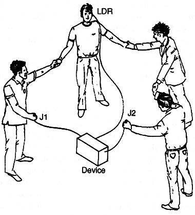
Basically, the project uses the LDR to “sense” light or images in an ambient and produce from them an electric signal that can be used to excite subjects as shown in Fig. 1.

The excitations consist of high-voltage signals (pulses or tones) applied to electrodes that can be touched by the subject or subjects. Figure 1 shows an experiment in which the subjects form a circle and, by joining hands, close the circuit such that all receive the stimulus produced by the circuit.
We should observe that the reader might have the false impression that the person who is touching the electrodes receives the most powerful discharge.
This is wrong. As the current flowing in the circuit is the same throughout, all persons receive the same discharge.
The circuit is powered from AA cells or a 9 V battery and can be placed in a very small plastic or wooden box for portable use. Current drain is very low, allowing the life of the battery or cells to extend many weeks or even months.
Experiments
- Experiments in ESP involve stimulation of the subject using the third eye. Using the device with several people as suggested in Fig. 150 can result in an interesting experiment.
- As in other experiments, the subject can try to alter the pulse rate or output voltage using his mind as a PK experiment. Light sources can be used as target of the subject with PK powers, and the LDR is used to detect changes in light intensity. In particular, we recommend using a candle because of its mystical implications.
- For transcendental meditation and biofeedback, this device can help the subject find the fourth state of consciousness or trance. The LDR can be placed in other locations such as focused on a point on the wall or a distant light source.
- In radiesthesia experiments, the influence of the pendulum on the subject or on an LDR placed in any location can be studied.
The LDR can be excited by the flickering flame of a candle to conduct an interesting experiment involving paranormal forces, ghosts, and spirits.
How It Works
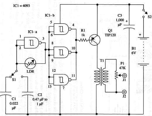
The circuit uses the same oscillator stage as the previous projects. One NAND gate of the four existing in a 4093 IC is used to produce pulses at a rate determined both by C1 or C2 and the resistance of an LDR or CD5 cell.
The amount of light falling on the LDR determines its resistance and therefore the frequency of the circuit. Frequency rises along with light intensity.
With C1 in the circuit, we have frequencies in the range of 200 and 5,000 Hz. Installing C2 in the circuit, the frequency becomes low-in the range of 0.2 to 5 Hz, producing interval pulses. The signals produced by this stage are applied to the three other gates that are wired as a digital amplifier (buffer-inverters).
The output of the amplifier stage drives a PNP medium-power transistor. As the load, this transistor has the low-voltage winding of a transformer. In the high-voltage secondary, we have the signals that are used to stimulate the subjects.
Using a common 117 Vac transformer, the output voltage can reach values up to 300 V. But, in this case, the current is very low, avoiding any danger to the subjects-although the sensation of shock can rise to very uncomfortable levels.
That is why we added a voltage control, formed by P1 in the output.
Assembly
The complete diagram of the third eye is shown in Fig. 2.

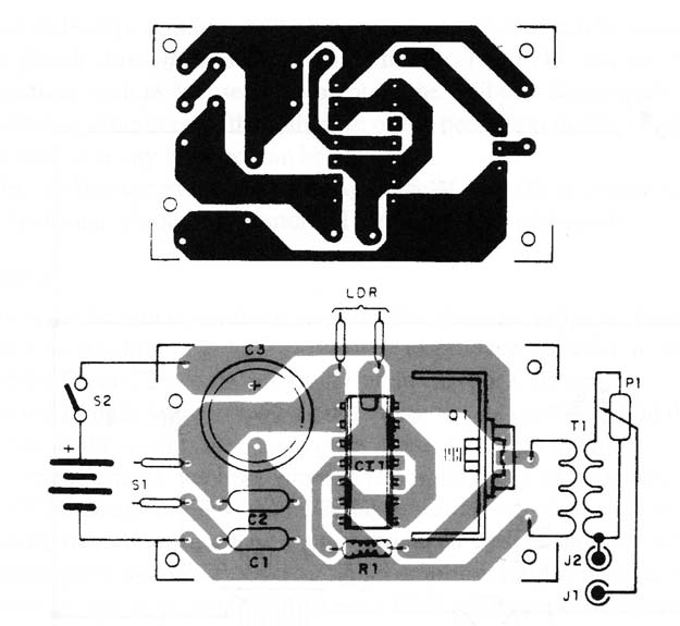
The circuit can be mounted on a small printed circuit board and housed into a plastic or wooden box as shown by Fig. 3.

Any medium-power PNP transistor with collector current rated to 1 A or higher can be used in this project. The transistor must be mounted on a small heatsink.
This heatsink is formed by a piece of metal bent to form a “U” or an “L.”
The LDR is another non-critical component. Any type with any diameter can be used in the project. The LDR can be mounted on a support to be affixed to the subject’s head and installed in a small cardboard tube. If a convergent lens is placed in front of the LDR, we add directivity and sensitivity to the circuit.
It will be able to pick up a small amount of light coming from distant or weak light sources.
The electrodes are made as in the previous project. You can use small metal plates affixed to the skin with a rubber band or, if you prefer, two metal rods placed in your hands.
The box dimensions depend on the power supply, as a battery is smaller than holder for four AA cells.
Testing and Using the Circuit
Place the electrodes on any part of your body or, if they are rods, hold them in one hand, but do not let one touch the other. Adjust P1 to the lowest output voltage. Place the LDR near any light source and turn on the power supply.
Place S1 in the position that connects C1 to the circuit. Test the circuit again with S1 in the other position.
Open P1 until you begin to feel a slight itch. Pass your hand in front of the LDR to see if the circuit changes its performance when the amount of light reaching the sensor is reduced. Then, to test the output of the circuit, open P1 more until the shock comes uncomfortable.
Now you can use the circuit in the experiments. Remember: every time you use the device, you must start the experiments with P1 closed. If you don’t, a potent shock will be applied to the subject when the circuit is turned on.
Note that you can also test the circuit using a neon lamp as indicator. When placed at the output of the circuit, it will glow when the voltage peaks at 80 V. A fluorescent lamp will also glow if plugged into the output of this circuit.
Suggestions
You can use only one value for C1. This way, C2 and 82 are not necessary in this project.
Powering the circuit from a 9 V or 12 V supply, you can increase the output power to use the circuit with fluorescent lamps. Do not use the circuit with human subjects if powering it from ac power supplies fed from an ac power line.
Replace the transformer with a coil formed by 20 to 100 turns of 28 AWG wire on a cardboard form. The circuit can be used to produce a magnetic field from the light on the sensor. This magnetic field can be applied to subjects of PK or ESP experiments.
Replace the transistor with any power FET such as the IRF640. No changes to the circuit are necessary to get the acceptable performance.
Semiconductors
IC1 - 4093 CMOS integrated circuit
Q1 - TIP32 medium-power PNP transistor
Resistors
R1 - 1k9, 1/8 W, 5%-brown, black, red
Capacitors
C1 - 0.022 µF, ceramic or metal film
C2 - 0.47 11F to 1 µF, ceramic or metal film
C3 - 1,000 µF/ 12 WVDC, electrolytic
Miscellaneous
LDR - Any light-dependent resistor or CdS cell (see text)
P1 - 47,000 ohm potentiometer
T1 –117 Vac x 6 to 12 V x 50 to 300 mA transformer (see text)
S1 - One pole x two positions, toggle or slide switch
S2 - SPST, toggle or slide switch
J1, J2 - Banana jacks
B1 - 6 V, four AA cells
Printed circuit board, plastic or wooden box, knob for P1, electrodes, cell holder,
wires, solder, etc.


