The kind of influence that a magnetic field can have on these experiments is speculative and not included in this discussion. But we should note that the common magnet has an important limitation: it produces a constant magnet field that. in some cases, is not strong enough for our purposes.
The magnetic field generator presented in this project can offer something more to the paranormal researcher. It produces a variable low-frequency magnetic field.
Several paranormal experiments can be performed with the aid of this project to explore the following subjects:
■ The influence of an alternating magnetic field when picking up sounds from paranormal sources
■ The influence of an alternating magnetic field when registering paranormal images
■ How ESP experiments are influenced by magnetic fields
■ The influence of the magnetic field in experiments involving Kirlian photography, telepathy, precognition, and psychokinesis/telekinesis
■ The influence of magnetic fields on plant growth and other physiological reactions of plants (Backster effect)
How It Works
The circuit is a low-frequency oscillator with a versatile configuration that can be used with several purposes, as the reader will see in this book. The low-frequency signal produced by the oscillator can be used to drive a coil, producing a magnetic field, or to drive a transformer, producing high voltage in Kirlian experiments.
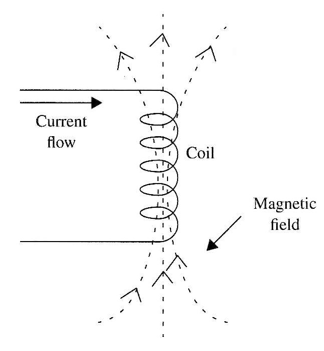
The operational principle is simple: when a current flows through a coil, a magnetic field is produced as shown in Fig. 1. The direction of the magnetic field lines depends on the current direction. As this circuit produces direct pulsed current, the direction is determined by the way the coil is connected. If required for a particular experiment, a switch can be added to invert the direction of the magnetic field.
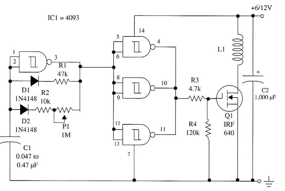
The frequency of the pulse current is also the frequency of the field and can vary in a range from several hertz up to 10,000 Hz. Capacitor Cl determines the frequency range and can be altered as suggested below. R1, R2, and P1 determine the frequency with Cl. The duty cycle is determined by R1, which can be chosen in the range between 4.7 and 47 kΩ. R2 and P1 determine the pulse rate or frequency. With the recommended values for Cl, the frequency is in the range be-tween several hundreds of hertz and several kilohertz. By reducing the value of Cl, the frequency can increase to values up to 1 MHz. The pulsed signal is applied to a power FET that drives the coil, producing large currents.
The circuit can be powered from supplies ranging from 6 to 12 V. The output power or intensity of the magnetic field depends on this voltage. You can use any of the power supplies recommended for other projects in this book as long as they have output voltages between 9 and 12 V and currents in the range between 500 mA and 2 A. Four D cells can be used to power the circuit, but only for short-term experiments, as the current drain is significant.
Assembly
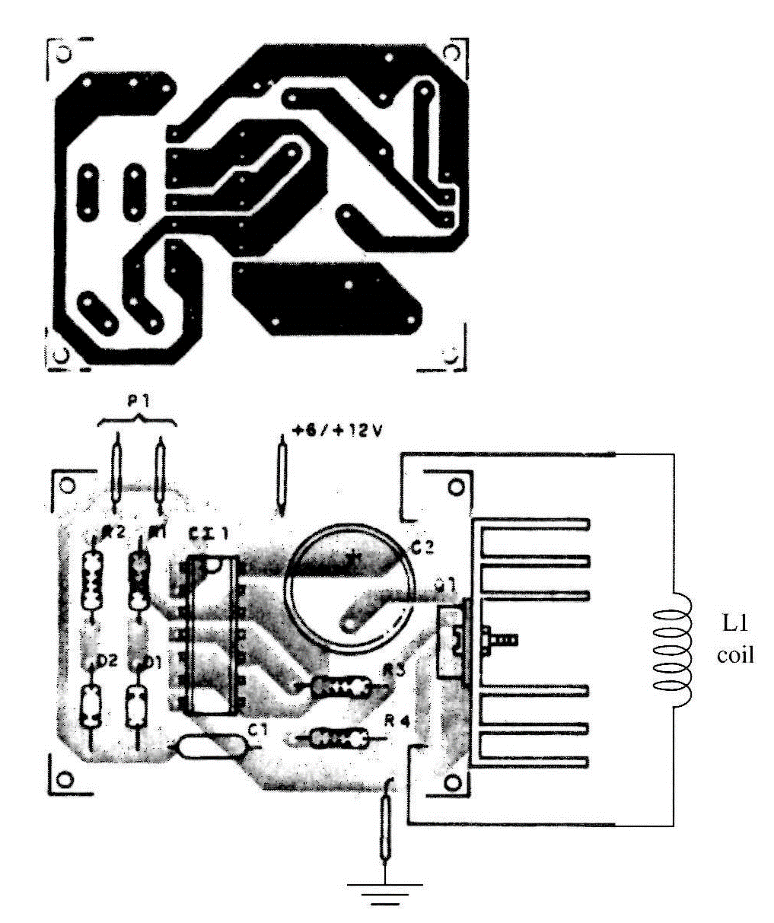
The complete schematic diagram of the magnetic field generator is shown in Fig. 2. A printed circuit board is used to support the basic components, as shown in Fig. 3. Any P-channel power FET with drain currents of 4 A or more can be used in this project. Types such as the IRF640, and many others in the "IRF" series, can be used. Types such as the IRF630, IRF640, and IRF720 are suitable for this project. An alternative is the use of an NPN Darlington power transistor with collector currents rated to 4 A or more.
The power FET needs a heatsink, made with a piece of metal bent to form a "U." The coil depends on the application the reader has in mind. To apply the magnetic fields to small subjects (such as plants, a person's hands, or even the head), the coil can be made as shown in Fig. 4.
On a cardboard or wooden form, 20 to 50 turns of enameled wire (28 to 32 AWG) are wound and plugged to the circuit using a 1 to 2 m common, plastic-covered wire.
Warning: Some studies have indicated that prolonged exposure to low-frequency magnetic fields can cause diseases such as cancer and leukemia in humans. But, at the same time, researchers also have discovered that some low-frequency magnetic fields can help to restore broken bones and, in some cases, accelerate the recovery of injuries in some people. If the reader intends to use this device to expose persons or living beings, it is advisable to proceed with great prudence. Don't expose yourself or others to the magnetic field for more than a few minutes when making any experiment.
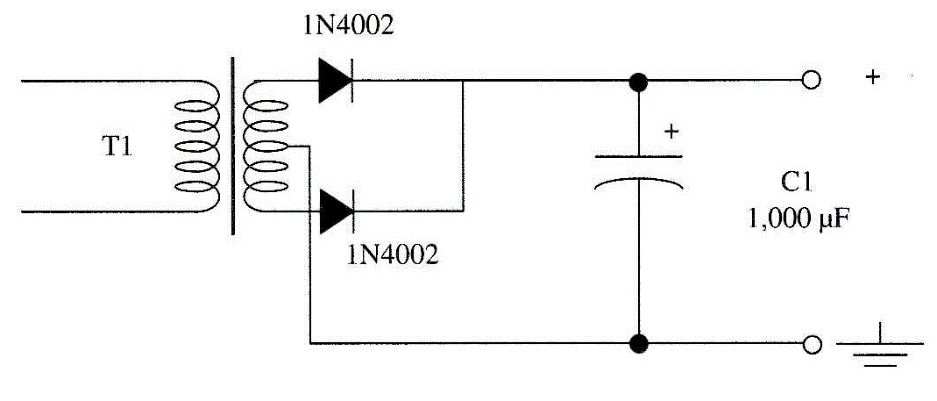
If the circuit is powered from the ac power line, the power supply shown in Fig. 4 can be used. The transformer has a primary winding rated to 117 Vac (or according to your ac power line voltage) and a secondary rated to 6 V to 9 V x 1 A. The diodes are 1N4002 or equivalents, and the electrolytic capacitor is rated to 12 WVDC. Although the transformer isolates the circuit from the ac power line voltage, it is important to take precautions to isolate all high-voltage components to avoid receiving shocks from any part of the circuit.
Testing and Using the Circuit
Turn on the circuit and, inside the coil, place a MW receiver tuned to a free point between 550 and 1600 kHz. You'll hear a tone if the circuit is operating, and a magnetic field is being produced.
The signals are picked up by the receiver at higher frequencies, as the circuit produces a rectangular current that is rich in harmonics extending up to the short-wave band.

To apply the magnetic field to any object or sample, simply place it inside the coil. Adjust the frequency according to what is desired for the experiment.
Suggestions
■ Living beings such as plants and insects can be placed inside the coil for a pre-determined time interval before beginning the experiments. The influence of the magnetic field can be studied by comparing samples that have and have not been subjected to the magnetic field.
■ The magnetic field can be used in ambient where voices and images are being picked up in paranormal experiments to see how it can influence the results.
■ D1, D2, and R1 can be removed. The circuit then will produce 50% duty cycle signals.
■ Replace the transistor with a Darlington bipolar NPN transistor such as the TIT'140, T1P142, or TIP142.
Semiconductors
IC-1 4093 CMOS integrated circuit
Q1 1RF640 or any power FET (see text)
D1, D2 1N4148 or equivalent—any general-purpose silicon diode Resistors
R1 47 kΩ, 1/8 W, 5%—yellow, violet, orange
R2 10 kΩ, 1/8 W, 5%—brown, black, orange
R3 4,700 Ω, 1/8 W, 5%—yellow, violet, red
R4 120 kΩ, 1/8 W, 5%—brown, red, yellow
Capacitors
C1 0.047 to 0.47 µF, ceramic or metal film
C2 1,000 µF, 16 WVDC, electrolytic
Miscellaneous
P1 1 MΩ potentiometer
L1 Coil (see text)
Printed circuit board, plastic box, wires, 28 to 23 AWG enameled wire for the coil, solder, etc. Materials for the Power Supply
D1, D2 1N4002 silicon rectifier diodes
T1 Transformer—primary according to the ac power line and secondary rated to 6 to 9 V CT, lA . Power cord, 1 A fuse, wires, solder, etc.


