An interesting article dealing with electric fish (The Electric Fish Named Black Ghost (BM027E)) shows that these animals produce electrical signals in the audible range from 700 to 2,100 Hz for orientation purposes in water. We can hear these signals if we connect to the aquarium they are in with a common audio amplifier and also pick up these signals for other purposes.
Our small amplifier lets us hear these electrical signals, making them audible sounds. Of course, there are other electrical phenomena which occur in living beings that, being in the audible range, can be converted into sound through the use of a small amplifier. We then describe in this article two small amplifiers which can be used in the lab to hear these signals on a small speaker.
Certainly, its use will arouse much curiosity and enrich any biology class. Both circuits are battery powered and therefore fully safe to use.
The Circuit
Both circuits consist of sensitive audio amplifiers which can work with the few millivolts of signals we encounter in the most common biological phenomena.
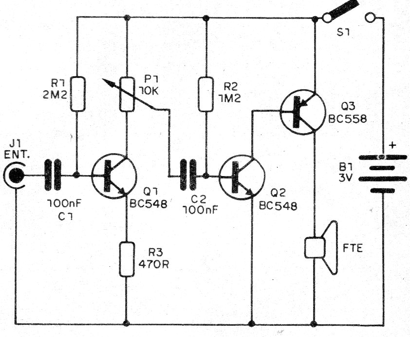
The first is quite simple, using three transistors capable of delivering a small amount of audio power to a speaker. We find a volume or gain control between the first and second stage and the circuit is powered by only two small batteries.
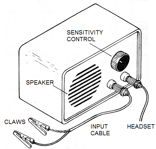
In Figure 1, we have a small box suggestion in which it can be built, observing that in this box we have a suggestion for using a headset.
The complete diagram of this amplifier version is shown in Figure 2.
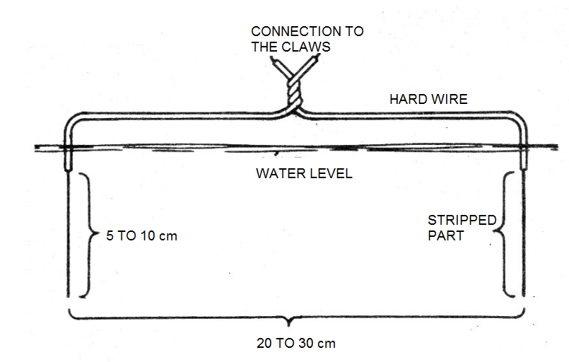
To hear signals of an electric fish (see article), we have in Figure 3 how to prepare the electrodes which should be placed in the aquarium.
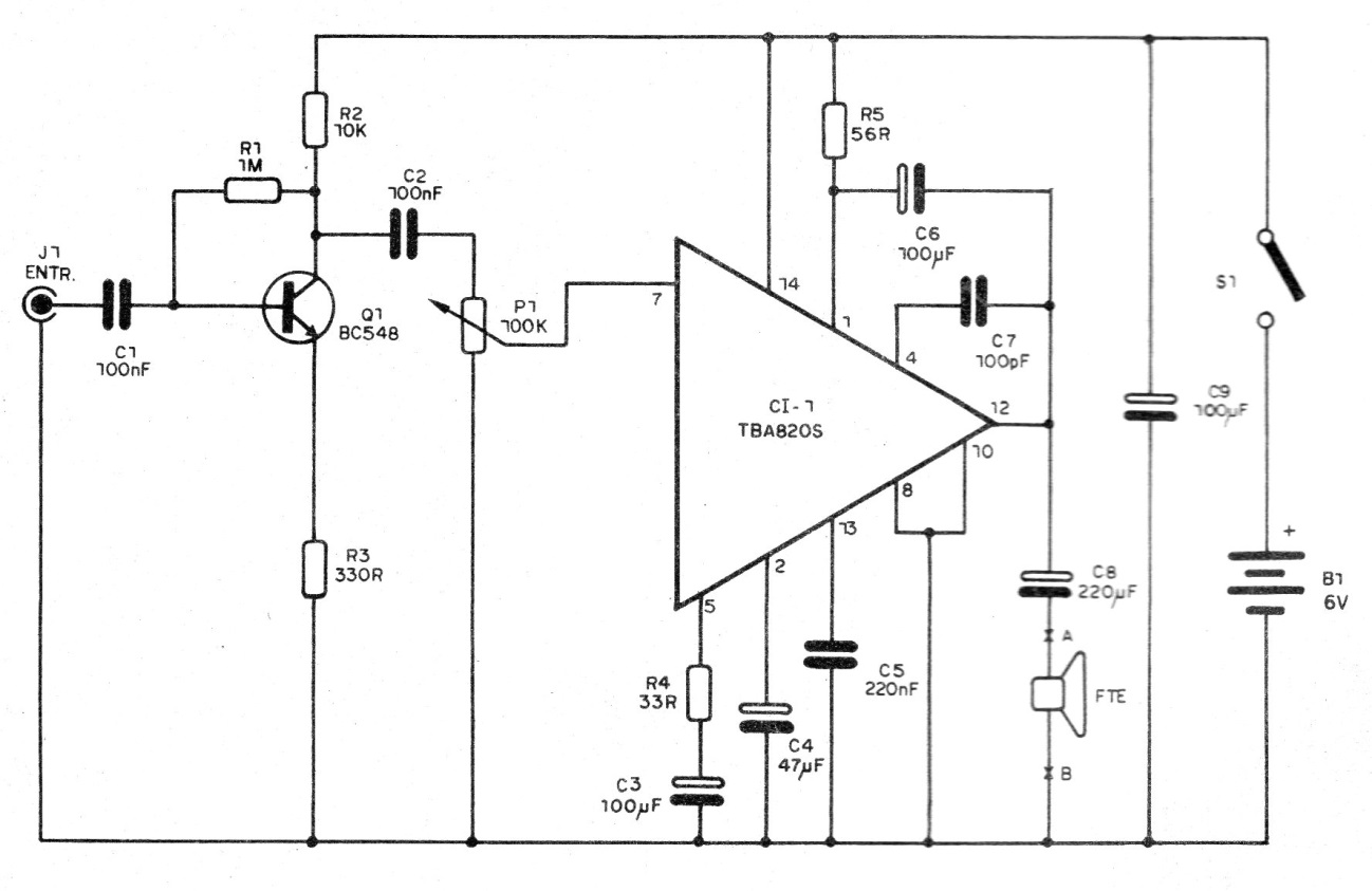
For the second version, we use a TBA820S integrated circuit.
This component is no longer as easy to find nowadays, but we can adapt the circuit to operate with today's most popular integrated devices like the LM386 and TDA7052. The circuit for this version is shown in Figure 4.
The printed circuit board for the transistor version is shown in Figure 5.
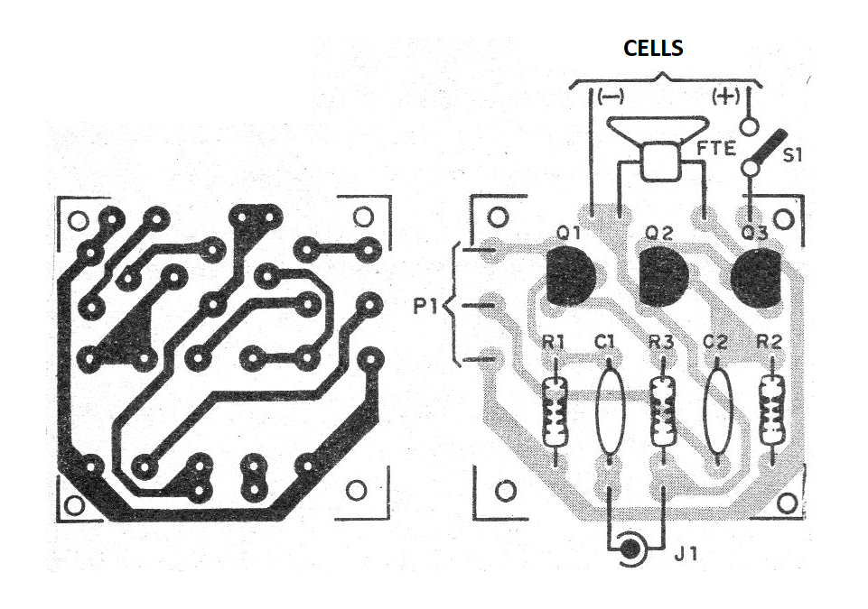
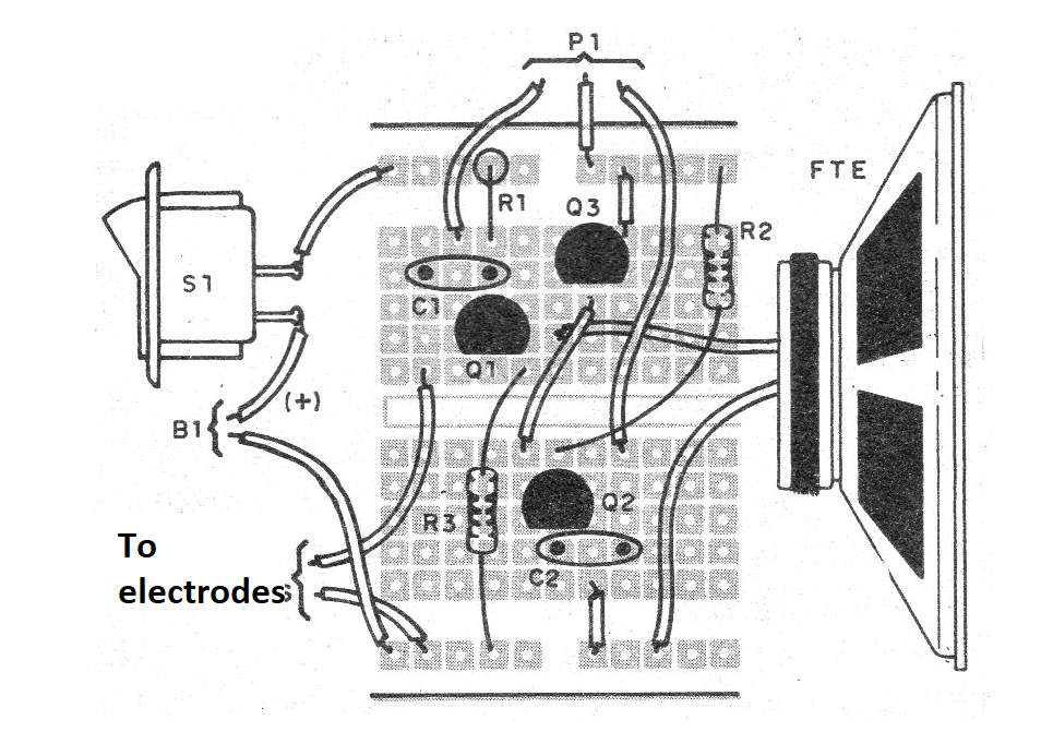
If the reader wants to make an experimental assembly on a breadboard, in Figure 6 we give the arrangement of the components.
When assembling, take a good look at the positions and types of the transistors, as Q3 is different from the others.
For the integrated circuit version, we have the printed circuit board in Figure 7.
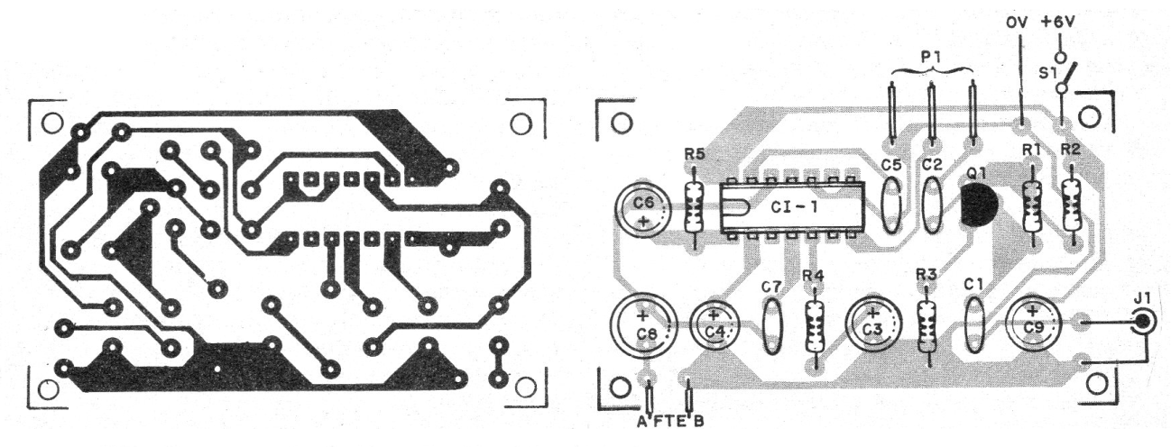
Note in this version the position of the integrated circuit and transistors, as well as the polarities of the electrolytic capacitors.
To test is simple: holding the input wire, our body picks up the noise of the power grid which turns into a snoring that is reproduced in the speaker.
a) Version 1
Q1, Q2 - BC548 - General Purpose NPN Transistors
Q2 - BC558 - General Purpose PNP Transistor
P1 - 10 k ohm - Potentiometer
FTE - 4 or 8 ohm - Small Speaker
S1 - Single Switch
B1 - 3 V - two small batteries
R1 - 2M2 ohm x 1/8 W - resistor - red, red, green
R2 - 470 ohm x 1/8 W - resistor - yellow, violet, brown
R3 - 1M2 ohm x 1/8 W - resistor - brown, red, green
C1, C2 - 100 nF - Ceramic or Polyester Capacitors
Miscellaneous:
Printed circuit board or breadboard, battery holder, wire, welding, etc.
b) Integrated version
CI-1 - TBA820S- Integrated Circuit
Q1 - BC548 - General Purpose NPN Transistor
FTE - 4 or 8 ohm - Small Speaker
S1 - Single Switch
B1 - 6 V - 4 small batteries
P1 - 100 k ohm - Potentiometer
R1 - 1M ohm x 1/8 W - resistor - brown, black, green
R2 - 10k ohm x 1/8 W- resistor - brown, black, orange
R3 - 330 ohm x 1/8 W - resistor - orange, orange, brown
R4 - 33 ohm x 1/8 W - resistor - orange, orange, black
R5 - 56 ohm x 1/8 W- resistor - green, blue, black
C1, C2, C7 - 100 nF- Ceramic or Polyester Capacitors
C3, C9 - 100 uF - Electrolytic Capacitor
C4 - 47 uF - Electrolytic Capacitor
C5, C8 - 220 uF - Electrolytic Capacitor
Miscellaneous:
Printed circuit board, mounting box, battery holder, wire, welding, etc.

