Note: this article, published in Brazil originally, was translated into English to be part of my book Bionics for the Evil Genius (TB – 2006).
Animals and humans use any source of light to see objects. The light reflected in the ambient media allows our eyes to form pictures of the objects we see.
Of course, any disturbance in the light that fills our surroundings or the presence of a light source with special properties can affect our behavior and the behavior of many other living beings.
One form of light that can cause unexpected behavior changes is stroboscopic light. The interaction between living beings and a stroboscopic source can result in interesting experiments and projects involving bionics.
A stroboscopic light is a light source that flashes from 0.1 to 10 times by second. You can mount one using an electronic circuit that will drive a common light source such as an incandescent lamp, a fluorescent lamp, an LED, or a xenon lamp.
Xenon lamps are the best for this application because they can produce very strong short-duration light pulses. such as the ones seen on police cars and ambulances. The advantage to the xenon lamp is that when using them as stroboscopic light sources, the flashes will be produced faster.
To help the reader conduct some experiments using stroboscopic light, in this article we will describes a basic project using a common incandescent lamp.
In the site the reader will find some after articles with other circuits of stroboscopic light sources using light-emitting diodes (LEDS), fluorescent lamps, and a even powerful version using a xenon lamp.
The Experiments in Bionics
When you see a flashing stroboscopic lamp at a party or a club, the interaction between you and that light source is very simple to explain: You have the sensation of a moment in time being “frozen” from that intermittent source of light. Why this phenomenon happens the reader can find in other articles in this site, but the importance of a light source in bionics experiments is that you can use it to discover many things about the behavior of many different living beings.
The following are some experiments you can perform involving the interaction between an electronic circuit that flashes a lamp and humans, animals, and plants:
What happens with a plant (even a tomato plant) if it grows under the illumination of a stroboscopic light source?
What changes in the behavior of a small aquarium fish if it is illuminated by a stroboscopic lamp? You can use this experiment to see how the frequency of the electric fish changes with a stroboscopic illumination. I
Illuminating the aquarium where the electric fish is, the frequency can be changed after some delay due to the induction of an uncomfortable situation.
Can you induce panic or other discomfort in others under the illumination of a stroboscopic light source? Yes. Placing persons in a room where the only light source is a stroboscopic lamp, a panic situation can be produced.
Can you use the modulation of a light source to transmit information, serving as a visual link between humans and a computer? For instance, you can modulate pulses produced by an LED to transmit sound from one place to other, using a phototransistor as receiver.
What is the limit of perception of frequency changes or the frequency of the flashes from a stroboscopic lamp sensed by a human being or animal?
What Is the Stroboscopic Effect?
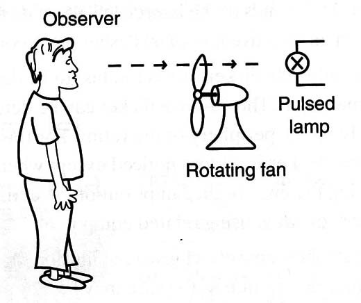
When a rotating electric fan is illuminated by a flashing light source so that a flash arrives as the fan blades are running, the blades will seem to stand still at a fixed position, as suggested by Figure 1.
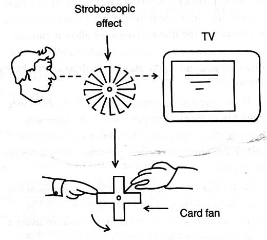
This is a useful way of observing fast-moving objects such as machinery or insect wings. If the flashes occur less frequently, the object will seem to move more slowly than its actual movement. You can observe this effect by rotating a small card fan in front of your TV, as shown by Figure 2.
Another way to observe the stroboscopic effect is to use a fluorescent lamp. This kind of lamp, operating on a 60 Hz alternating current, goes on and off 120 times per second. The light from the lamp would go out completely, except that the phosphors have some phosphorescent or “carry-over” action. That is, they continue to glow for a short time after the existing radiation is cut off.
This variation in light output is known as flicker. The flicker rate for a fluorescent lamp is 120 cycles per second. At the ends of the lamp, each alternate flash results in an effective rate of 60 flashes per second.
The 120-cycle flicker rate is too fast to be detected by human sight. The 60-cycle flicker can be detected, but only by the periphery of the retina. For this reason, lamp flicker is seldom noticed except when observing the ends of the lamps out of the corner of one,s eye or when using related equipment.
The stroboscopic effect gives the illusion of motion or no-motion as the case may be. For example, it was thought that the pulsating effect of an alternating current operating at 60 Hz produced a flicker, which when used on deteriorating machinery would appear to indicate that the machinery was slowing down or even stationary.
The danger of the stroboscopic effect is self-evident, but with modern fluorescent tubes the problem has been minimized by reduced flicker effect and should not cause problems. In some industrial situations, it is common for the ambient light source to be in opposition of phase and therefore to not have the presence of the stroboscopic effect.
The Circuit
Common incandescent lamps are very slow when it comes to producing stroboscopic flashes. Such lamps cannot offer more than five flashes a second, because the inertia of the filament does not allow it enough time to return to the cold state, make small temperature changes, and create another flash, as shown by Figure 3.
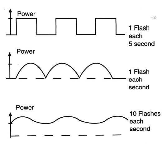
If an incandescent lamp produces flashes at a rate higher than four or five per second, the lamp will begin to flicker. Crossing the 10-flashes barrier, the flicker will not have enough amplitude to be detected by our eyes.
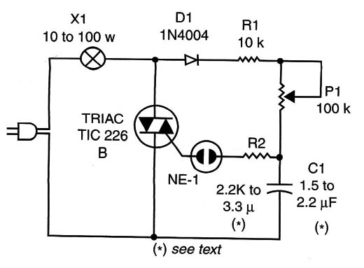
So for our circuit, using incandescent lamps in the range between 0 and 4 or 5 Hz will be useful. The basic circuit consists of a relaxation oscillator using a neon lamp and a TRIAC circuit.
The load is an incandescent lamp with power capabilities of up to 150 watts.
When the circuit is powered on, the capacitor C1 charges across D1, R1 and P1. It charges until it reaches the trigger voltage of the neon lamp, about 80 volts.
At this moment, the neon lamp conduces (or begins to let the electric current pass across it), and the capacitor C1 discharges through the gate of the TRIAC. The TRIAC conduces for a moment, power ing the lamp used as a load.
The flash lasts until the charge of the capacitor reduces the gate voltage to a value that is enough to keep the TRIAC on. At this moment, the TRIAC turns off and a new cycle of operation begins.
R2 controls the speed of Cl’s discharge and thus the duration of the flash. The reader is free to find the best value for this component. Values that range from 2.2 to 10 k ohm must be tested if the flashes are not powerful enough for the application.
The circuit can also be operated from the 220/240V AC power line. It is enough to replace D1 by an 1N4007 and the TRIAC by a TIC226D.
How to Build
Figure 4 shows the basic version of the schematic diagram for the stroboscopic lamp.
Since few components are used, the circuit can be mounted on a small printed circuit boardp, as shown in Figure 5.
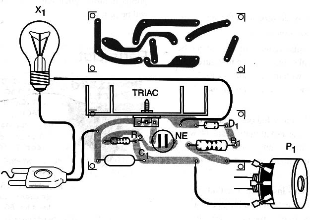
The TRIAC must be mounted on a heatsink, mainly if the lamp is powered at higher than 60 watts. Remember that the circuit is not isolated from the power supply line, so any exposed part can cause severe shocks.
Place all the parts inside a plastic box. Only the lamp will be placed externally, and a long pair of wires can be used to wire the lamp to the circuit.
Lengths of up to 10 meters will not cause any problems for the circuit’s operation. You can use color lamps or wire many lamps in parallel because the sum of the power Will not pass the maximum value allowed by the circuit.
Testing and Using
First, plug the circuit into an AC power line. Adjusting P1, the lamp will flash at different rates, so find the best effect.
If the power of the flash is not high enough, change R2. Higher values will result in longer light pulses, but the higher limit of the frequency range Will be reduced.
TRIAC: TIC226B TRIAC for 117 VAC or equivalent (TIC226D for 220/240 VAC)
D1: 1N4004 silicon rectifier diode (1N4007 for 220/240VAC)
NE-1: NE-2H or equivalent neon lamp
X1: 10 to 150 W incandescent lamp according to the AC power line
R1: 10 k ohm x 1/8 W resistor, brown, black, orange
R2: 2.2 k ohm or 3.3 k ohm x 1/8 W resistor, red, red, red or orange, orange, red
P1: 100 k ohm or 220 k ohm lin or log potentiometer
C1: 1.5 to 2.2 µF x 100 V or more polyester capacitor
Other parts: PCB or terminal strip, heatsink for the TRIAC, power cord, knob for P1, wires, solder, etc.


