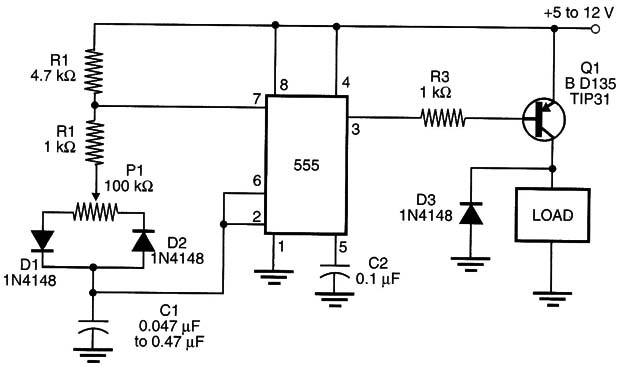
Figure 1 – PWM with the 555 IC
The transistor is chosen according the current drained by the motor. The same components must be valued experimentally to achieve a correct match with the motor’s characteristics. Darlington PNP transistors can be used in this circuit; replace R3 with a 4.7 or 10 k ohm resistor.


