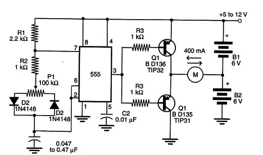
The NPN transistor conducts the current provided by B2 when the output of the 555 is at the high logic level, and the PNP transistor conducts the current provided by Bl when the output of the IC is at the low logic level.
The reader can also use Darlington transistors in this control by increasing the value of the resistors at the transistors, bases from 1 k ohm to 4.7 or 10 k ohm.
Care must be taken when choosing the correct values for C1. This capacitor value can be established experimentally to match the characteristics of the motor, thus avoiding vibration when it is at the zero-power drive condition. A capacitor with values between 0.01 and 1 µF can be wired in parallel with the motor to avoid this vibration.
Remember that the great disadvantage of this kind of control is that, at the zero-power drive condition, the currents delivered by the power supplies are not zero, and a great deal of heat can generated in the motor. This kind of circuit is not suitable for the control of resistive loads such as heaters, SMAS, and others.


