The circuits shown in the next lines can be used as shields for microcontrollers such as the Arduino, PIC and MSP430. In some cases changes the base resistors must be made.
The power supply for the stages can be different from the voltage used to power the microcontroller.
The voltage for the stages depends on the voltage of the controlled load.
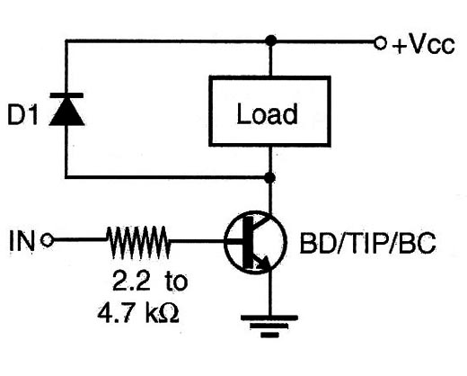
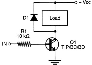
If you are controlling a relay (50 to 500 º, up to 100 mA) or any load up to 100 mA, the transistor can be a BC547, BC548, or equivalent. The BD135 can control loads up to 1 A, and the TIP31 up to 2 A. These transistors are mounted on a heat sink.
R1 is used to limit the base current. The circuit will turn on when a voltage between ] and 12 V is applied to the input. A current of about 100 A is necessary to drive this circuit when using the BC548.
In the same figure, we show how a switch can be used to control this circuit.
Sensors such as LDRs can also be used, replacing the switch.
Switching with a PNP Transistor
The circuit shown by Figure 2 can drive the same loads as the previous blocks.
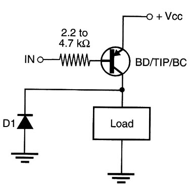
The PNP transistor used for loads up to 100 mA can be the BC558. For loads up to 1 A. use the BD136 or BD138, and for loads up to 3 A, the TIP32 or even the TIP42.
The load is turned on when the input is connected to ground, or a negative voltage is applied. With an input current of about 100 “A, loads up to 100 mA can be driven, depending on the transistor gain. This sensitivity is enough to allow the use of resistive sensors as LDRs. The diode is necessary when driving inductive loads.
Using an NPN Darlington Pair
Two directly coupled NPN transistors can increase the gain of a driver stage as shown by the block in Figure 3.
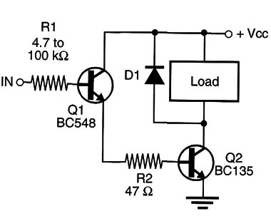
The gain of the stage is the gain of Q1 times the gain of Q2. With a few milliamperes, it is possible to drive high-current loads such as motors, solenoids, and relays.
Q1 can be any NPN general-purpose silicon transistor such as the BC548 or 2N2222. Q2 depends on the current of the load. For sensitive relays (up to 50 mA), the BC548 or 2N2222 can be used.
When driving directly loads up to 1 A, use the BDl35 or BD137 and, when driving larger loads up to 3 A, use the TIP31 or TIP4l mounted on a heat sink. Diode D1 is necessary when working with inductive loads.
The input resistor depends on the signal source. When the input receives a positive voltage between 2 and 12 V, the load is turned on. A few microamperes are necessary to drive the circuit. An LDR can be used to excite this stage.
Using a PNP Darlington Pair
The equivalent configuration of the previous block, using PNP transistors, is shown by Figure 4.
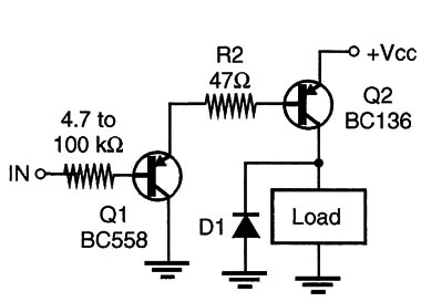
For loads up to 50 mA, use the BC558 or any general-purpose silicon PNP transistor.
For loads up 1 A use the BD136 or BD138 and for loads up to 3 A, the TIP32 or TIP42.
The circuit is driven when the input is connected to ground by a switch, any resistive sensor, or an external circuit. A few microamperes are necessary to turn on the load. The diode is also required when driving inductive loads.
Using a Darlington NPN Transistor
Instead of using two separated transistors to form a Darlington pair, it is possible to use a device that contains two transistors wired as a Darlington pair.
These devices are called Darlington transistors, and they can be found in NPN rather than PNP form. Figure 522 shows how an NPN Darlington transistor can be used to drive a load as shown in the previous blocks.
The transistor shown is a TIPI 11 that can control currents up to 1 A. It has a current gain as high as 1,000. This means that an 1 µA current in the input can cause a 1 A current in the load. As in the equivalent NPN block, the load is on when & positive voltage is applied to the input.


