We've already covered in several articles the working principle of the PWM controls which are much better than the linear controls that present losses.
If you want to know more about the working principle of these controls, which is the same from the circuit shown in this article see more articles in this site.
How it works
In our circuit, we do is the traditional control, by changing the active cycle of a rectangular signal according to the power that we want to apply to the engine.
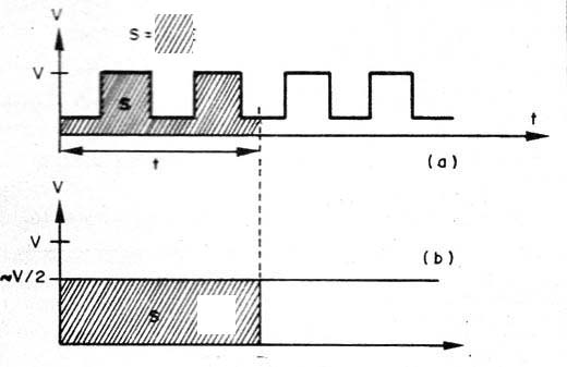
Figure 1 shows that in a control by pulses, what matters is the area of ??the figure covered by the graph, as it determines the power applied.
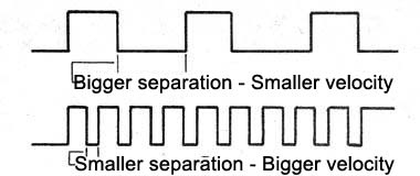
Thus, to control the applied power, we simply generate a rectangular signal and change the width of the pulses, or their separation, as shown in Figure 2.
To generate signals with active cycles that can be controlled we use one of the triggering ports of the integrated circuit 4093, as shown in Figure 3.
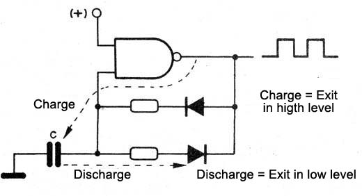
In this circuit, the capacitor charging current is performed by a diode and it determines the time at which the output signal is at high level.
Moreover, the discharge is made by the other diode, which determines the time in which the output is at the low level.
As the resistors are associated with these diodes to determine the time, if one is variable, we can control both the duration of the pulses as the separation.
This is precisely what we do in our circuit by connecting in series with one of them a pot of control, which will be the speed control.
The signal generated by this circuit is digitally amplified and applied to a transistor which switches a LM350T regulator integrated.
This 3-terminal regulator can control currents up to 3 A, and been then digitally modulated by the oscillator.
At the output we have the voltage pulses that can be applied to a load up to 3 A.
Assembly
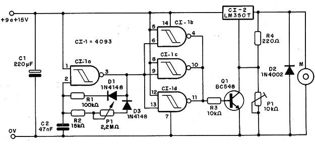
In Figure 4 we have the control of the complete diagram PWM.
In Figure 5 we have a suggested printed circuit board for the assembly.
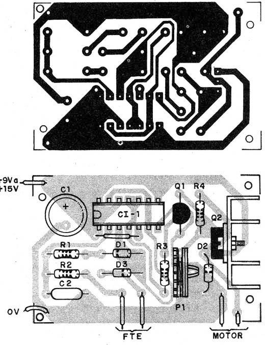
The LM350T integrated circuit should be provided with an appropriate heat sink.
For other components note the positions of the 4093 integrated circuit, of the transistors and of the diodes.
The resistors are 1/8 W and the pot can be lin or log.
Test and Use
To test, connect to the engine output of 6 to 15 V with a maximum current of 3 A.
Power the circuit with the engine rated voltage and adjust P1 to check the speed, refinishing the minimum point P2 (trimpot).
If the motor tends to vibrate too much, which may occur in some cases, change the value of C2, operating in another frequency range.
Proven the operation, you only need to use it, within the circuit current limit.
The circuit can also operate as a dimmer for heating elements and incandescent bulbs or LED sequences with reduced resistors.
CI-1-4093 - Integrated circuit
CI-2 - LM350T - Integrated circuit
Q1 - BC548 – general purpose NPN transistor
D1, D3 - 1N4148 - Silicon diodes
D2 - 1N4004 - Silicon diode
P1 - 2M2 Ω - pot
P2 - 10k - A trimpot
R1 – 100 k Ω x 1/8 W - resistor - brown, black, yellow
R2 - 15 k Ω x 1/8 W - resistor - brown, black, green
R4 - 220 Ω x 1/8 W - resistor - red, red, brown
C1 - 220 µF x 25 V - electrolytic
C2 - 47 nF - ceramic capacitor or polyester
Miscellaneous:
A printed circuit board, a radiator for the IC,a box for the assembly, wires, welding, etc.


