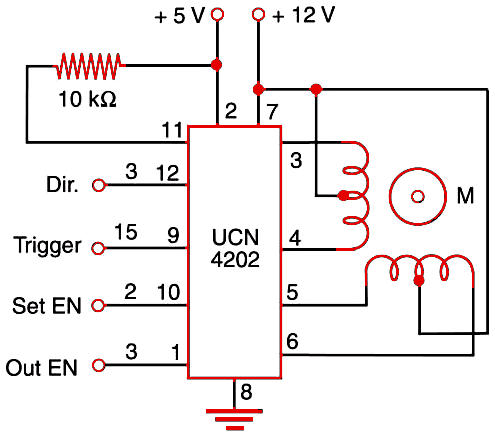
Stepper motors with up to 500 mA per winding can be controlled by this circuit, without the aid of any driver transistor stage. If the current requirements of the motors are higher, you can add one of the driver blocks shown at the beginning of this chapter.

This IC’s control inputs are as follows:
The direction determines if the motor runs forward or backward, according the logic level.
The trigger enable is where the control pulses are applied, determining the speed of the motor.
In the step enable, you can brake the motor, as in the output enable.


