If the reader works with high resistance and does not have a multimeter able to measure them here is a good fitting suggestion: one megohmeter.
With it is possible to measure resistances up to 47 megΩ with good accuracy without the need for special meter or any additional action.
The accuracy depends on the components used and usually is within the tolerances of the measured own devices.
The circuit is powered by 4 small batteries or 9 V battery. Durability of the elements used in the source will be very large since the test is fast which means a use for a few seconds in most cases.
The indication is made by LEDs which makes it extremely cheap circuit. In fact, a compact assembly makes the same size as a common multimeter type of low cost fully portable.
The use of the device is also very simple and does not require any calculation or complex procedure.
Characteristics:
* Scale: 2 (up to 4.7 M Ω, and 47 Ω M)
* Power supply: 6 or 9 V (battery or battery)
* Operating type: Bridge
* Current drain: 5 to 10 mA (typ)
HOW IT WORKS
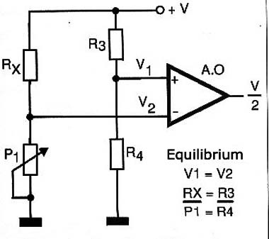
The circuit is nothing more than a bridge that must be balanced with the resistance to be measured.
The resistors R3 and R4 form a divider that applies the non-inverting input of an operational amplifier with high input impedance, a tension of the order of 1/10 of the supply voltage.
The resistance to be measured along with the resistance presented by the potentiometer selected by switch S2 form a second voltage divider that applies voltage to the inverting input of the operational amplifier.
If the voltage applied to the inverting input is less than the operating reference the reference the output voltage goes to a high level and turns on LED2. On the other hand, if the voltage applied to the inverting input is greater than the operating output of the reference voltage goes to low level the LED1 remains off it.
In equilibrium conditions when the voltages are equal LEDs light up simultaneously. In practice this tension can not be achieved easily due the high gainof the operational it is difficult to balance. However, it is possible to precisely identify the point of transition when a LED is off and the other light.
Thus, moving the pot, we see that the voltage balancing circuit occurs exactly when the resistance presented by the potentiometer corresponds to 1/10 of the placed Rx resistance in the circuit.
Spurn this case R1 which is only added to prevent, in the case of probes are joined (no resistance) and potentiometers are in the lowest resistance position, the power supply is placed in short. Figure 1 shows what occurs in this equilibrium condition.

As we known the resistance of the potentiometers used in the balance we can calibrate its scale in terms of Rx. So to pot the 4.7 M Ω just divide your turning into 10 parts each corresponding to 4.7 M Ω which leads us precisely to the larger scale of 47 M Ω.
P2 simply divide your turning into 10 parts each with 470 k Ω, thus obtaining the maximum range of 4.7 M Ω.
Of course the precision of measurement will depend both on the precision of the component to R3 and R4 of the resistors used in the reference divider.
ASSEMBLY
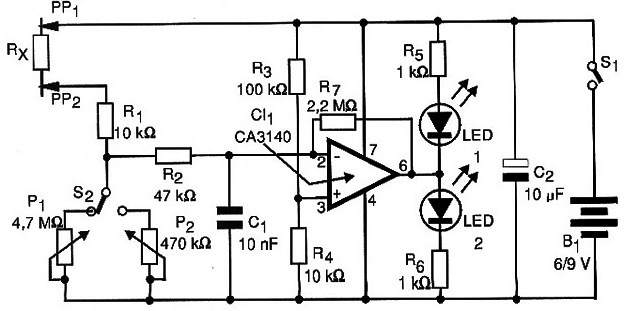
In Figure 2 we have the complete diagram of the megohmeter.

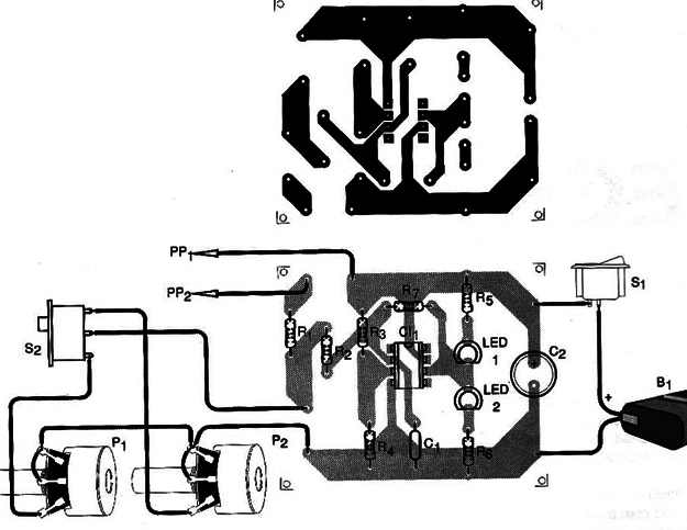
The arrangement of components on a printed circuit board is shown in figure 3.

Probes must be well insulated and connected with short wires to the circuit since any contact or leakage can affect a resistance that can be seen by the circuit.
LEDs may be two common red or one red and one green.
Pots should be linear good quality because of them depends on the accuracy of the measurement.
For R3 and R4 the player has two options to improve accuracy: one is to select with the multimeter in a lot of two resistors that have values ??closer to the desired. Another option is to use units of 1% or 2% accuracy, if they can be easily found in your dealer.
For the integrated circuit is recommended to use a socket. They may be experienced with equivalents using input FET such as the TL series from Texas.
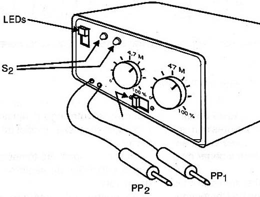
In Figure 4 we have a suggestion box for assembly, observing the scales of pots.

For the power supply must be used appropriate or connector support.
All resistors are 1/8 W and the capacitors are not critical to the ability of a modified values ??are more than 100% range.
TEST AND USE
Connect between the probes a 4M7 resistor and set the switch S2 in the position that selects P1 (larger scale).
Connect the device in S1 and slowly go spinning P1 until you obtain the switching of the LEDs. Place P1 to stay as close to the point at which this occurs. It should be read on the scale a close value of 4.7 M Ω corresponding to the resistor under test.
To use never touch the probes during testing not to introduce changes in the value of resistance measured.
Always choose the scale according to the strength of the order of magnitude to be measured.
Semiconductors:
CI-1 - CA 3140 - Integrated circuit, FET inpout operational amplifier
LED1, LED2 - red LEDs or other color
Resistors (1/8 W, 5%)
R1, R4 - 10 KΩ
R2 - 47 kΩ
R3 - 100 K ohm
R5, R6 - 1 kΩ
R7 - 2.2MΩ
P1 - 4.7 MΩ - linear potentiometer
P2 - 470 kΩ - linear potentiometer
Capacitors:
C1 - 10 nF - polyester or ceramic
C2 - 10 µF / 12 V - Electrolytic
Miscellaneous:
PP1, PP2 - probes with alligator
S1 - Single switch
S2 - Key 1 pole x 2 positions
B1 - 6 or 9 V - 4 batteries or battery
Printed circuit board, plastic box, buttons for pots, scales for pots, battery holder or battery connector, wires, welding, etc.


