Code locks are interesting devices, especially if the reader has read the Da Vinci Code (Book) and has a special attraction for this type of device. The lock that we describe uses 4 keys (or more) that must be placed in a secret combination of positions so that, when pressing the release button the lock opens, as shown in figure 1.
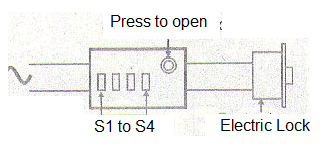
If a different combination is triggered, pressing the button touches a buzzer or alarm.
How it works
The circuit is based on the operation of so-called switches or two-way switches that are used to drive corridor and stairwell lamps, as shown in figure 2.
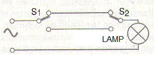
In this circuit, we can turn on or off the controlled lamp by acting on any of the two switches (or switches), placed at the ends of a corridor or staircase. To obtain this type of drive, 1-pole x 2-position switches are used which can be found with facilities in the houses of electrical materials. The idea is to use these keys to program a binary type drive code, such as 0101 where 0 means a position and 1 other position, as shown in figure 3.
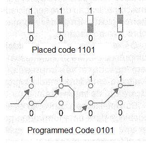
Thus, if the keys are placed in the positions corresponding to the programmed code, the current finds a path to the lock that is completed when we press the push-button switch.
In a simple version we can only use the combination to trigger the lock, but we can use the additional functions to activate an alarm. For this purpose 4 diodes are used which, if one of the keys is not in the correct position, when the pushbutton is pressed, the one receiving the power is the bell or alarm.
Assembly
In figure 4 we have the complete diagram of our coded lock.
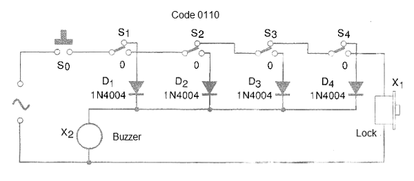
The actual appearance of the assembly is shown in figure 5. Note that we do not need a printed circuit board because this is very simple assembly.
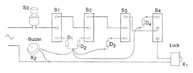
The keys are of the two-way type and must be placed in a panel for external fixation. If the site is exposed to weather, care must be taken to ensure that there is no risk of rainwater penetration.
The diodes are 1N4004 rectifiers if the mains is 110 V and 1N4007 if the mains is 220 V. The lock is of the magnetic type of doors which makes use of a solenoid. Of course, the device can also be used to trigger other things like call systems, disable an alarm, etc.
The lock is of the type according to the local network. There is the possibility of locking the circuit by ringing an alarm if the wrong key combination is set and the push button is pressed. This is done with the circuit of Figure 6 which uses an SCR.
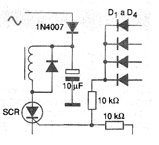
To reset the circuit, simply press the switch in parallel with the SCR. Avoid using alarms with simple cicadas that can burn if they stay too long. Lastly, we remind you that this circuit is connected directly to the power grid and that all care must be taken so that there are no exposed parts capable of causing dangerous shocks.
D1 to D4 - 1N4004 or 1N4007 - silicon diodes
S1 to S4 - Two-way switches
S5 – Push buttonswitch NA
X1 - Electric lock
X2 – Lock according to the power grid
Miscellaneous:
Wires, solder, box for assembly, etc.


