What happens is that when a motor with three-phase power fails to receive one of the phases, the thermal elements of the motor-drive key, which are connected in series with the control coil, disarm the circuit, turning off the key.
However, if the motor does not make too much effort at certain moments of its operation, one of the phases missing, the contacts that have been adjusted for larger loads may not work and with this we will have the problem of the operation missing a phase, able to burn the motor.
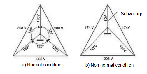
The circuit described is interesting and can also be used in single-phase motors and other applications sensitive to undervoltages. In figure 1 we show what happens with the voltages in a three phase motor when one of the phases is missing.

Thus, it is enough to monitor the voltage (instead of the current) in order to deactivate a circuit in case of undervoltage, when the normal elements do not work, in case of light loads in three-phase motors.
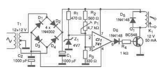
Of course, other circuits can be protected, including appliances such as refrigerators, washing machines, etc. It is also possible to reverse the action of the relay, using NF contacts and setting the trip voltage to values ??of 125 V, in which case the circuit will act as an overvoltage detector. In figure 2 we show the configuration used, which are nothing unusual.

What we have is an operational amplifier connected as a comparator, where the reference voltage is given by the zener diode. Thus, when the input voltage is above the reference voltage we have a practically zero voltage at the output of the operating.
When the input voltage drops to a lower value than the reference voltage, the operational amplifier switches and its output has a positive voltage, practically the same as that used in its supply. This causes the transistor to be polarized to saturation by energizing the relay.
The trimpot P1 adjusts the tripping voltage as a function of the secondary voltage of the transformer / rectifier source when the input voltage drops below a certain value. This adjustment can be made with a Variac in order to obtain the exact trigger point, using a common multimeter on the alternating voltages scale. The relay used must have contacts in accordance with the controlled current.
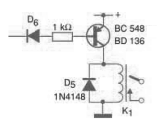
If the circuit is intended for tripping overvoltages, a relay with NF contacts must be used or the tripping must be modified to use a PNP transistor as shown in figure 3.

The transformer used is not critical, and types with secondary from 7.5 V to 12 V with currents of 100 mA to 500 mA can be used without problems, since the adjustment allows the trip to always be made at the desired voltage. Only the relay must be suitable for it to be tripped with the voltage supplied by the circuit. The zener diode is also not critical, as it only provides the reference for the P1 setting. 3.3 to 6.8 zener diodes can be used without problems. Operational amplifiers equivalent to 741 may also be employed, including types that operate with less voltage, in which case the secondary voltage of the transformer may be even lower. A suggestion of printed circuit board for the assembly, in which case a 10 A relay with reversible contacts was used.
If the relay used is different, appropriate changes in the design of the board must be made. In figure 4 we give the connections for the protection of a three-phase motor, using two units, as described in this article.

Material list
CI-1 - 741 - operational amplifier, integrated circuit
Q1 - BC548 or equivalent - general purpose NPN transistor
D1 to D4 - 1N4002 - rectifier diodes
D5, D6-1N4148 - general purpose diode
Z1 - 4.7 V x 400 mW - zener diode
K1 - 12 V x 50 mA relay - contacts according to controlled load
R1 - 470 ohm x 1/8 W - resistor
R2 - 560 ohm x 1/8 W - resistor
R3 - 330 ohm x 1/8 W - resistor
R4 - 1 k ohm x 1/8 W - resistor
C1 - 1000 uF x 25 V - electrolytic capacitor
T1 - Transformer with primary according to the local grid and secondary 12 + 12 V x 300 mA
Miscellaneous:
Printed circuit board, power cable (optional), mounting box, wires, load connection terminals, solder, etc.


