The 741 Operational Amplifier is still the heart of many projects being preferred when you want to unite the ease of practical realization at low cost.
This project that we present, although it is not new in terms of new things may be the solution that the reader looks for to elaborate a selective filter for a remote control or other interesting application.
What we have is basically a sensitive circuit that responds to audio signals from a single frequency. The sensitivity of the circuit allows the activation with signals of amplitude of some tens of millivolts which allows its connection in the output of common receivers of remote control without intermediary stages of amplification.
Another important application that enters the research sector is the recognition of an analog value (frequency) that can be transmitted at a distance (telemetry).
The circuit consumes a very low current at rest but needs a symmetrical power supply.
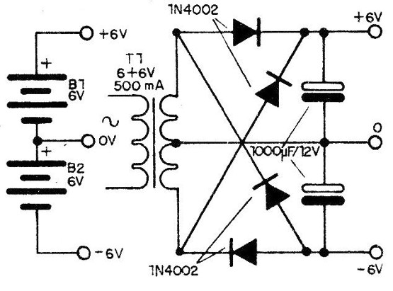
In figure 1, we show how to obtain the symmetric voltage of 12 V (6 + 6 V) from two 6 V batteries or from the local grid.
The frequency at which the drive occurs depends on the components of the double T, which can be changed over a wide range of values. Frequencies between 100 and 10 000 Hz can be achieved, but we remind you that in a practical application in which two circuits are used simultaneously they can not be tuned to multiple frequencies (harmonics), since there may be erratic activation.
Likewise, the Q factor or circuit selectivity does not allow the use of very close frequencies.
Each channel should be at least 30% away from the other channel.
HOW IT WORKS
The base of the circuit is a double T, which has a resonance frequency given by the values of the components according to the formula next to the diagram of figure 2.
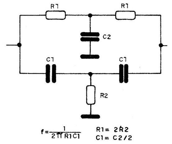
Note that components must maintain specific relationships between them to make the circuit work properly.
For the components used in the main design we have an operating frequency around 700 Hz.
The frequency limit for stable operation with good gain is around 10 kHz. The higher throughput will be in the frequencies around 1 kHz.
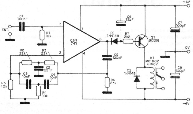
The double T is connected between the output and the inverting input (-), so as to provide a strong negative feedback.
Thus, the gain of the circuit drops except at the operating frequency when the double T has a high impedance and therefore reduces the negative feedback.
At the output of the circuit we connect a diode that polarizes the base of a transistor through R7 and the capacitor C6.
The diode and C6 rectify and filter the amplified signal that appears at the output of the integrated so as to have a continuous polarization of the transistor to drive the relay.
Without the capacitor, when applying a signal in the circuit, the contacts of the relay would vibrate with an improper operation.
The suggested relay allows the control of loads from 2 to 4 amps which leads to applications of small and medium power.
C7 and C8 uncouple the power supply and the input is made from the non-inverting input.
ASSEMBLY
The complete diagram of the apparatus is given in figure 3.
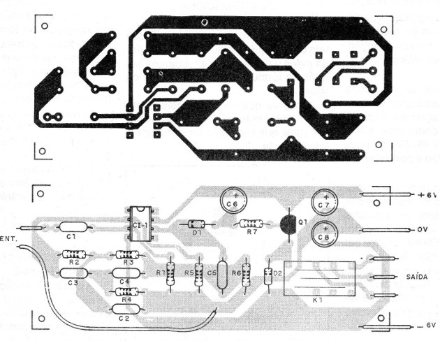
The printed circuit board shown in figure 4 provides for the use of a DIL micro-relay (12 V) with two reversible contacts.
The diodes are commonly used in silicon such as 1N4148 or 1N914 and the transistor can be any commonly used silicon PNP. The electrolytic capacitors must have working voltages of 12 V or more and the resistors are all 1/8 W.
Operational amplifier 741 should preferably be installed in a socket D1L both to avoid heat in the welding process, as well as, to facilitate exchange if necessary.
The capacitors of the double T, as well as C1 and C5 can be both polyester and ceramic.
The capacitors of the double T, must have the values ??chosen according to the desired frequency for the operation.
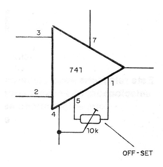
Operational amplifiers may have a leakage current that unbalances their output, even in the absence of a signal, thereby triggering the relay without signal.
If this occurs the circuit of figure 5, it should be used for off-set current adjustment.
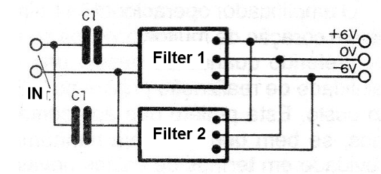
Several circuits like this can be connected in parallel and fed by the same source in the development of a tone-driven remote control system, as shown in figure 6.
When mounting, carefully observe the polarity of the diodes and the power supply.
TEST AND USE
An oscillator with integrated 555 whose diagram is shown in figure 7 serves as a test generator and for determining the operating frequency of the relay.
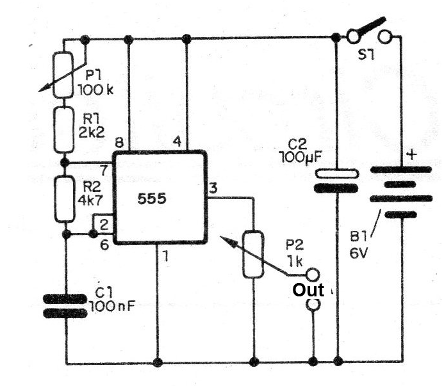
Adjust the frequency control of the generator until the relay is activated and then look for the center frequency while adjusting the oscillator frequency and reducing the signal strength.
The exact point of operation can then be determined by reading at a frequency if the reader has this type of instrument available and desires a precise reference of the operation.
The drive sensitivity can also be determined by this same procedure by reading the minimum signal strength at the output of the generator that triggers the drive.
This can be done with the help of an AC voltmeter or even with an oscilloscope.
A better determination of sensitivity and frequency can be achieved with a sinusoidal signal generator.
Checking the operation of the appliance is only for practical use.
CI-1 - 741 - operational amplifier - integrated circuit
Q1 - BC558 - PNP silicon transistors of general use
D1 and D2 - 1N4148 - silicon diodes of general use
K1 - 12 V x 50 mA Relay
R1 and R4 - 10k x 1/8 W - resistors (brown, black, orange)
R2 and R3 - 22k x 1/8 W - resistor (red, red, orange)
R5 - 10k x 1/8 W - resistor (brown, black, orange)
R6 - 27k x 1/8 W - resistor (red, violet, orange)
R7 - 2k2 x 1/8 W - resistor; (red, red, red)
C1 - 100 nF (104 or 0.1) - ceramic capacitor or polyester
C2 - 22 nF (223 or 0.022) - ceramic or polyester capacitor
C3 and C4-10 nF (103 or 0.01) - ceramic or polyester capacitors
C5 - 120 nF (123 or 0.12) - ceramic or polyester capacitor
C6 - 22 uF x 12 V - electrolytic capacitor
C7 and C8 - 100 uF x 12 V - electrolytic capacitors
Various: printed circuit board, symmetrical power supply, socket for the integrated (and relay), wires, solder, etc.


