
ART2972S ART168
This type of device can be seen in public restrooms quite frequently: the approach of hands to the faucet causes it to be activated automatically, releasing water for a certain time. Besides avoiding touching the faucet, which is somewhat unhygienic, this type of device prevents it from being used for longer than necessary or being left open. Other applications can be suggested for the same device, such as:
* By training your dog, it can learn that when it approaches the valve, water will be released and it can drink without problems. An automatic water fountain can be designed in this way.
* On an assembly line, a product that needs a jet of water can receive it simply by passing in front of the sensor.
* At a pool entrance, a shower can be activated for a few moments when passing in front of the sensor, as suggested in Figure 1.
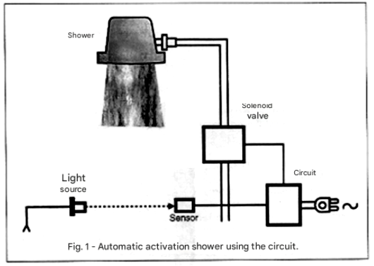
Obviously, there is no limit to the possible applications of this device, including modifying the input circuit to use other types of sensors. The circuit is powered by a 12-volt supply from a small source, and its consumption is very low in standby mode. Higher consumption occurs only when the relay is energized. We must also consider the safety of the drive circuit, which is completely isolated from the power grid.
HOW IT WORKS
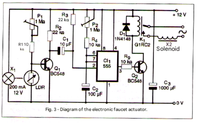
What we have is basically a monostable multivibrator with the well-known 555 integrated circuit, which is activated when the light beam incident on an LDR is cut off. In this configuration, the trigger input of the 555 (pin 2) is kept high by resistor R3. With the LDR illuminated, transistor Q1 remains cut off, and thus capacitor C1 has both terminals high. It remains discharged.
By momentarily cutting off the light beam incident on the LDR, the transistor is biased to conduct (sensitivity is adjusted by P1). With this conduction, the armature connected to the transistor's collector goes low, causing the capacitor to charge via R3. This is sufficient to momentarily bring pin 2 of the 555 IC to a low level, triggering it. Upon triggering, pin 3 (output) of the 555 goes high, saturating transistor Q2 and thus energizing the relay coil. The relay will remain energized for a time interval that depends on the adjustment of P2, the value of R4, and also C2. Capacitor C2 can have values ranging from 100 uF to 1000 uF to obtain time intervals ranging from a few seconds to more than 15 minutes. The choice of this capacitor will depend on the circuit's application. The relay activates a solenoid of the type used in washing machines. This solenoid is nothing more than an electric water valve, as shown in Figure 2.
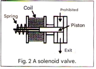
When the solenoid is not energized, a strong spring keeps the valve closed and no water can flow. When the solenoid is energized by the mains voltage, the plunger is pulled, thus releasing the passage of water. This type of solenoid valve can be easily acquired both in washing machine repair shops and can even be obtained from a machine that is no longer in use.
ASSEMBLY
Figure 3 shows the complete diagram of the device.
The arrangement of the components that make up the electronic circuit on a printed circuit board is shown in Figure 4.
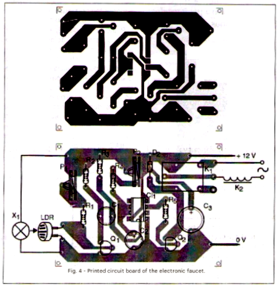
The relay accepts equivalent components, which, however, may require modifications to the circuit board design. It will be advisable to have the relay on hand beforehand, and only then create the final printed circuit board design. Any common round LDR can be used. The LDR should be mounted in an opaque tube so that it receives light only from the driver lamp. This lamp can focus its light on the LDR by means of a lens placed in front of it, and it can also be mounted in an opaque tube.
Depending on the application, a larger lamp, connected to the mains power supply, for example, can be used. The resistors used are all 1/8W or larger, and the electrolytic capacitors must have a minimum working voltage of 16 volts. Equivalent transistors and diodes are acceptable. The solenoid is of the type used in washing machines or equivalent, depending on the desired application. The assembly can be easily installed in a small box with wires going to the sensor, lamp, and solenoid, in addition to the power source, which is the local mains. Please note that the wires to the solenoid must be well insulated as they are directly connected to the power supply. Figure 5 shows a power supply for this circuit that can be housed in the same box.
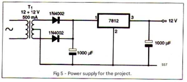
The integrated voltage regulator circuit has a small heat sink since the higher current will only be required during the intervals when the relay is energized. The power supply transformer has a primary winding according to the mains voltage and a 12+12V secondary winding with a current of at least 500 mA.
TESTING AND USE
To test the device, simply connect it to the mains power and adjust P2 to the shortest timing (lowest resistance). Leave the LDR illuminated and adjust P1 to the trigger point. You should hear the solenoid clicking when this occurs. Reverse the adjustment of P1 slightly and wait for the solenoid to disengage. Passing your hand in front of the LDR should trigger it. Once operation is verified, simply install the device permanently and then readjust for optimal performance.
Suggested modification
For readers who do not wish to use a relay, it is possible to activate the solenoid using a TRIAC as shown in the circuit in Figure 6.
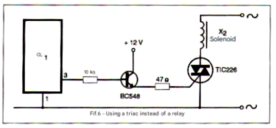
The TRIAC can be a TIC226B if the mains voltage is 110V or a TIC226D if the mains voltage is 220V. However, it's important to remember that in this configuration, there is no longer isolation between the sensor circuit and the power supply.
Bill of Materials
Semiconductors:
IC-1 - 555 - integrated circuit, timer
Q1, Q2 - BC548 or equivalent - general purpose NPN transistor
D1 - 1N4148 or equivalent - general purpose diode
Resistors: (1/8W, 5%)
R1, R4, R5 - 10 k ohms
R2, R3 - 22 k ohms
P1, P2 - 1 M ohms - trimpots
Capacitors:
C1 - 10 uF/16 V - electrolytic
C2 - 100 uF to 1000 uF/16 V - electrolytic
C3 - 1000 uF/16 V - electrolytic
Miscellaneous:
X1 - 12V x 200 mA lamp - see text
LDR - common round LDR
K1 - 12 V relay G1RC1 or equivalent
X2 - Washing machine solenoid
Printed circuit board, mounting box, integrated circuit socket, wires, solder, etc.


