
ART3893S ART5494
Note: Links to many articles on the website are at the end of this one, and we also suggest typing 2N3055 in the search. This article is from June 2024.
The 2N3055 Transistor
This important power transistor, which became the "daddy" of them all, was created by RCA (Radio Corporation of America) in the 1960s using a new technology, homotaxial.
This technology replaced epitaxial, which until then had been the most widely used in the manufacture of power transistors. At that time, good portions of power transistors were still made of germanium.
The original 2N3055 was made of heavy metal and had a TO-3 package, as shown in the figure.
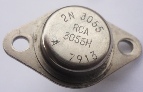
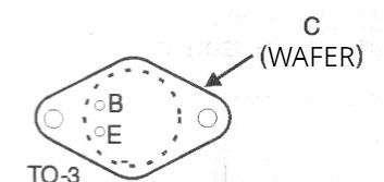
In this metal enclosure, as is typical for this type of component, the collector was connected to the housing. The wafer was in contact with it in the collector region, thus facilitating heat transfer to the heat sink. Figure 2 shows the terminal layout.
However, as time went by, the 2N3055 became so popular that other versions, other manufacturers and, of course, counterfeit versions appeared that still flood our market today.
Features
The original 2N3055 had a high heat dissipation capacity and could operate with currents up to 15 A.
Many thought that "those 15 A" were just a matter of course, forgetting that the operation of any semiconductor device, such as transistors, was subject to certain limitations set by what we call the SOA (Safe Operating Area), as shown in Figure 3.
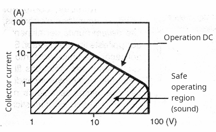
The 2N3055 is designed to operate with up to 100 V collector voltage and has a maximum dissipation of 115 W. However, if you input 100 V and make it conduct 15 A, it is easy to see that 15 x 100 = 1500 W. The transistor would have to dissipate 1500 W, and it only manages 115. It would certainly burn out.
Thus, the voltage can reach a maximum up to a certain point, as we can see from the graph. Increasing the current decreases the maximum voltage, and there is a limit. Thus, at a typical 60 V, the maximum current will be only 2 A.
For this reason, many are under the illusion that they can make a 12 V power supply with 15 A with just one 3055. This is not possible. For normal applications, we should not use more than 5 A.
If we want more current, we need to connect several of them in parallel. We will see how to do this later.
The World of the 2N3055
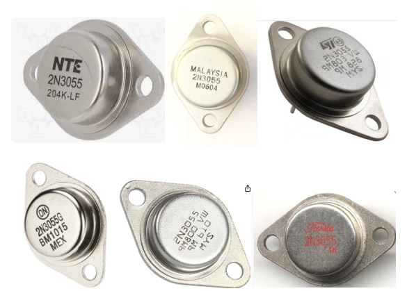
An early, economical version used an aluminum housing, which, however, had slightly lower heat dissipation capacity, requiring care, especially when the component was pushed to its limits. Several manufacturers also entered the lucrative market represented by this component, as shown in Figure 4.
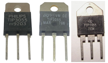
A plastic version with lower dissipation also appeared, the TIP3055 manufactured by Texas Instruments, ST, Philips and others, which was also and is still successful today.
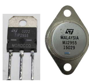
Finally, we have the complementary, that is, the equivalent PNP type that soon appeared to enable the use of the pair in complementary amplifiers, for example. In Figure 6, the MJE2935 and the TIP2935.
Heatsink
An important point to consider when using the 2N3055, its various versions, and its accessories is the heatsink.
The 2N3055 transistor is bipolar, and the amount of heat generated is determined by the product of the current flowing and the voltage difference between the collector and emitter.
It gets really hot and needs to transfer the heat generated to the environment. Using an appropriate heatsink and installing it correctly is essential to prevent it from overheating and burning out. Figure 7 shows how to install the metal 2N3055 on the heatsink. The website also has instructions for installing the plastic version.
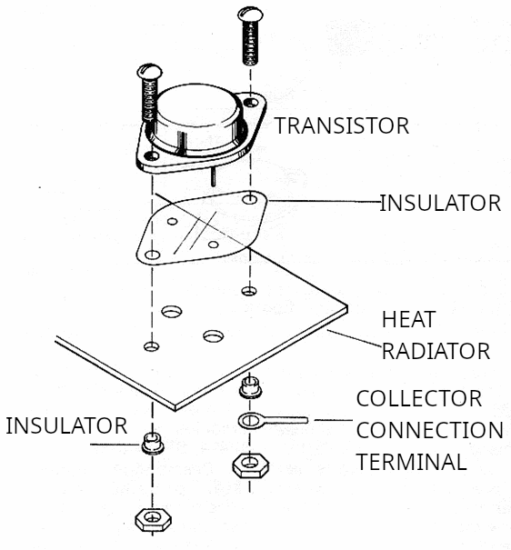
The best insulator is mica, but silicone, which is an excellent heat conductor, can also be used. Paste between the transistor and the insulator and between the insulator and the heatsink is recommended.
Be sure to use insulating bushings (insulators) to prevent the transistor from accidentally moving during assembly and its terminals from touching the heatsink, causing a short circuit.
Fakes
But we also have fake versions sold by dishonest suppliers who, in turn, buy from dishonest manufacturers or buy in batches of dubious origin, often re-stamping a similar transistor (but with different characteristics) with the name 2N3055.
Figure 8 shows an example of a real 2N3055 transistor and a fake one when opened. Unfortunately, they are not sold in transparent packaging so we can verify this!
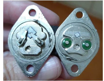
Note the width of the contacts, which are much wider on the real one. These contacts also dissipate heat, meaning the real one is more efficient. The fake one uses extremely thin wires for these contacts, which can't also act as heat sinks.
However, the most striking fact is the chip dimensions. They determine the current and dissipation capacity of the component, which is noticeably smaller on the right-hand type.
In short, fake types exist, and other characteristics can reveal this gain, transition frequency, etc.
Connecting in Parallel
We should not require more than about 5 A from a 2N3055 in an application. If we need more, we should connect them in parallel, but this isn't a simple and straightforward process.
If we connect two 2N3055s to control a 10 A current in a power supply, we can't guarantee that the current will be divided equally between them. Transistors have small differences in gain, for example.
If one transistor passes 7 A and the other 3 A, not only will one of them heat up more than the other, but the overloaded transistor could burn out.
One way to ensure that the current is distributed equally between the transistors is to connect a very low-value resistor to their emitters, so as not to significantly alter the current, as shown in Figure 9.
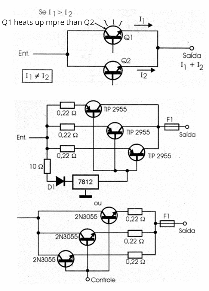
Wire wound resistors from 0.10 to 0.47 ohms with dissipations around 2 W are the most recommended for this application.
Modern and Equivalent Versions
The 2N3055 is still useful and can be salvaged from scrap or even purchased on sale, which can help with a simple project. However, there are modern versions of the same type of transistor that offer higher performance.
However, be careful. An equivalent is not always equivalent. What we can have is a substitute. Therefore, there are transistors that can replace the 2N3055 in some applications, but not all.
When choosing a transistor to replace the 2N3055, we must consider the application. Many support the same current, have higher dissipation, but have lower gain. Others have the same current and even higher voltages, but the cutoff frequency can be much lower, and so on. Below is a list of possible substitutes for your 2N3055 in a project. 2SB1942
2SC5200
2N3772
MJE13007
MJ2194G
BDY73,


