
ART3985S ART5566
Note: Article published in Saber Eletrônica magazine, issue 463, July/August 2012
Installation components, equipment, and the electrical system itself can be affected by the presence of harmonics. Irreversible damage can occur in many cases.
The effects of harmonics in a network manifest themselves in various ways. In some cases, they can be heard as unusual oscillations or vibrations in the devices being powered. In other situations, they can be detected by overheating or even voltage fluctuations, affecting the brightness of the lamps illuminating the area. However, most can only be effectively detected with the use of appropriate instruments. Let us analyze these effects.
Overheating
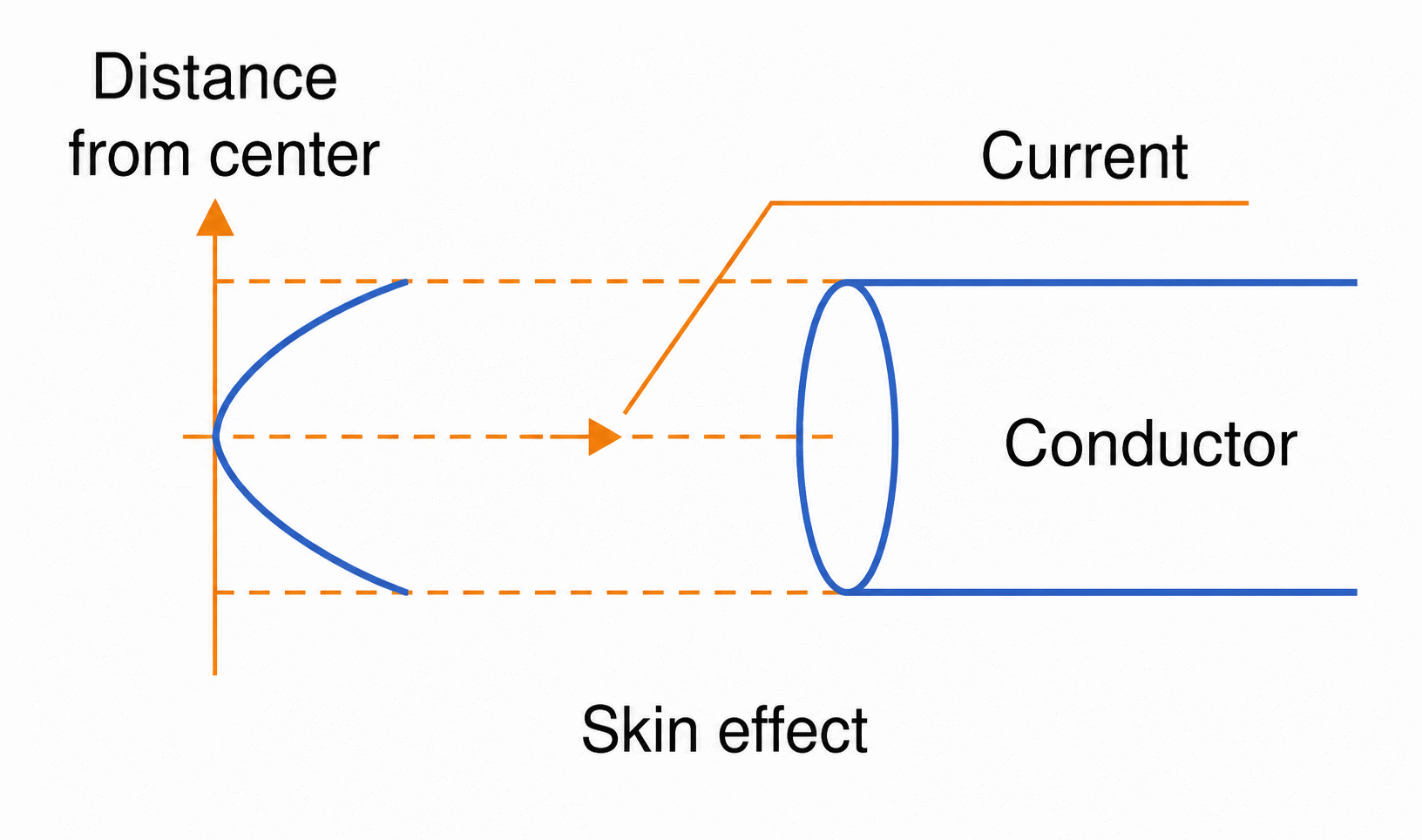
Harmonics can have frequencies many times higher than the fundamental signal. Due to the skin effect, higher-frequency currents tend to flow through the outer layers of the conductor. This means that the resistance encountered (due to the uneven distribution of the current) will be greater, resulting in greater heating, as shown in Figure 1.
Protection System Operation
The effective current values may be small, but if the crest factor is high, given the presence of harmonics, the protective devices will trip, even if the current in the circuit appears to be lower than necessary. This is important in cases where computers are powered by a common network and equipment with characteristics capable of generating harmonics and, therefore, frequently tripping circuit breakers. Separate circuits or uninterruptible power supplies (UPS) are recommended to prevent data loss in the event of a power outage.
Resonance
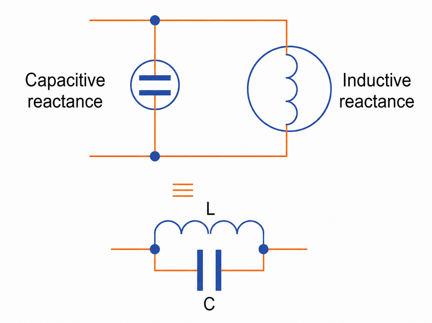
Inductive loads in parallel with capacitive loads can form an LC resonant circuit, as illustrated in Figure 2. Capacitor banks used to correct the power factor of certain installations form resonant circuits with inductive loads, capable of amplifying certain harmonics present in these networks.
Voltage and Power Factor Changes
Another effect caused by the presence of harmonics in a network is increased voltage drops and a reduction in the power factor.
What to Do to Correct the Problems?
If problems caused by the presence of harmonics are detected in a network, several actions can be taken to correct them. Below, we detail some of them.
Care for Phase and Neutral Conductors
The criteria of the NBR5410 standard should be the basis for sizing conductors. The standard provides for the ideal scenario in which there are no harmonics.
However, the circuit current must take into account the presence of harmonics, considering that it can reach up to three times the value of the phase currents (see Figure 3).
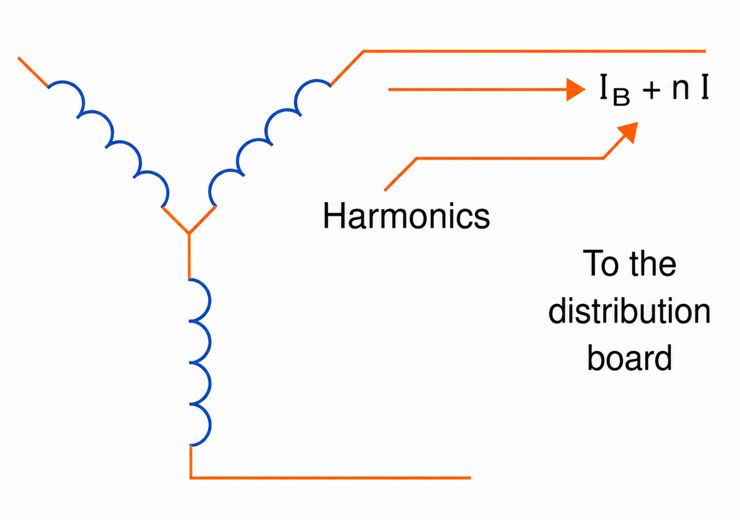
Therefore, instead of the standard's recommendation that the neutral conductor be half the cross-section of the phases, in some cases, this conductor must be even thicker than the phase conductors, given the presence of harmonics must.
Failure to properly size this conductor can lead to overheating and even problems with the powered device itself. This leads us to basic procedures for determining conductor cross-sections for three-phase circuits where harmonics are present, especially third-order harmonics in the phases. It was also assumed that the conductors are made of the same materials.
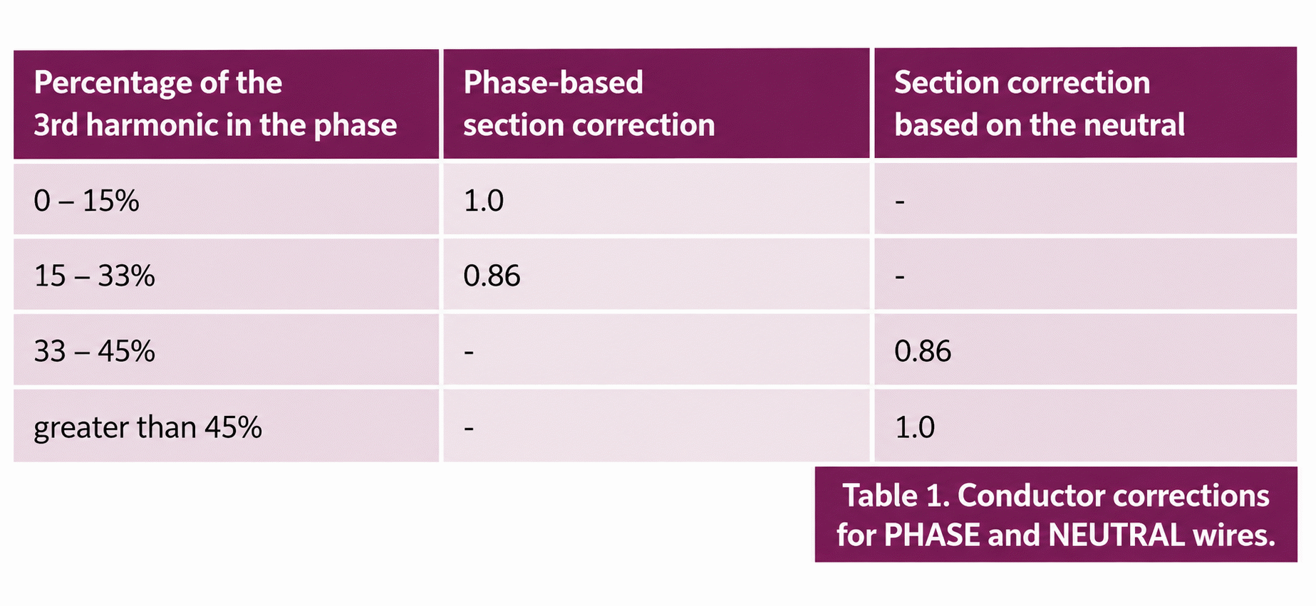
These procedures consist of correcting the recommended cross-sections according to the presence of harmonics, as shown in Table 1. This correction applies to three-phase circuits with four conductors. This table should be used in conjunction with tables 31 to 34 of NBR5410/97.
Filters
Controlling the presence of harmonics in an installation is vitally important to ensure the proper operation of the devices it supplies. A low THD means having a waveform as close to sinusoidal as possible. Internationally, a 5% limit for the presence of these distortions at all points in an installation is recommended. Standards such as IEC 61000-3-2, IEC-3-4, and IEEE 519-2 specify the THD limits that must be met in an electrical installation.
The values of THDU and THDI (Voltage Harmonic Distortions and Current Harmonic Distortions) are interconnected. This means that the processes used to reduce them can operate with both quantities. The processes used to reduce THDI and THDU are essentially threefold.
Using Inductances
In this case, an inductance is connected in series with the powered device, as shown in Figure 4.
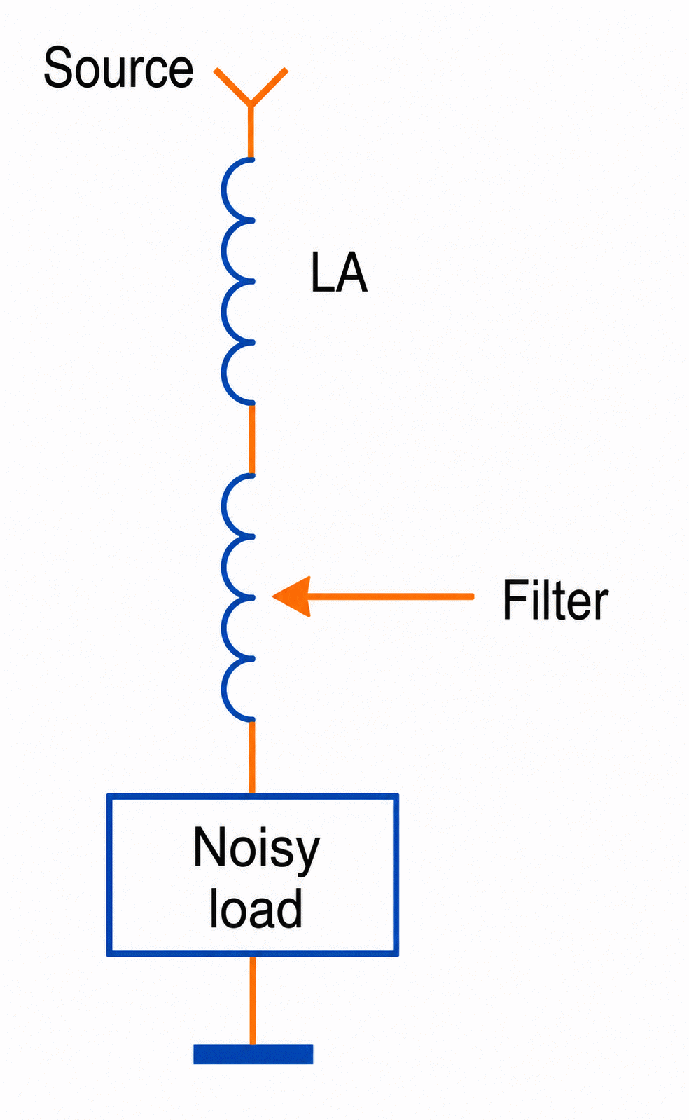
The added inductance is added to the inductance of the cable and the source (transformer or generator), thus attenuating higher-frequency signals, which correspond precisely to harmonics. Switching-mode power supplies used in computers and other devices use this technique.
Although this solution has limited efficiency and, depending on the application, its dimensions can be large, in addition to causing a certain voltage drop in the line, its main advantages lie in its simplicity and its usability with virtually any type of source.
Passive Filter
In this case, as shown in Figure 5, an LC filter is connected in parallel with the powered circuit, which is responsible for energy pollution. The values of the elements in this circuit must be such that the filter's impedance is zero at the frequency of the harmonic to be eliminated. This filter is also called "uncompensated."
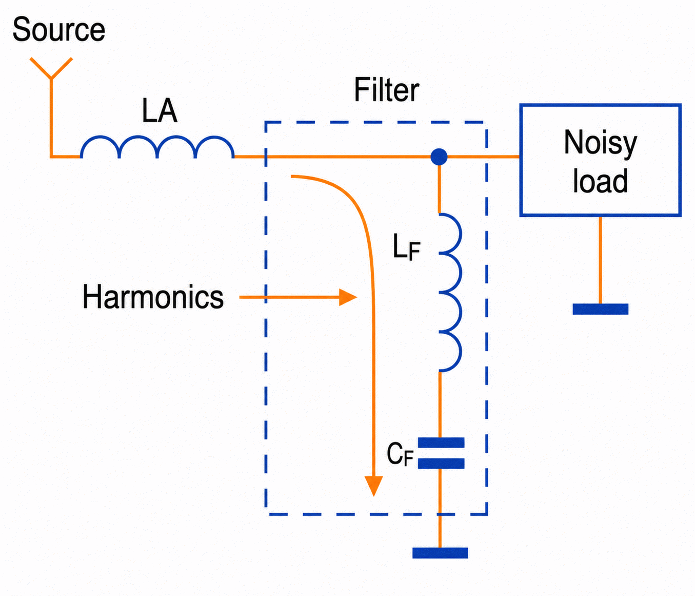
Another type of LC filter is the compensated one, configured as shown in Figure 6.
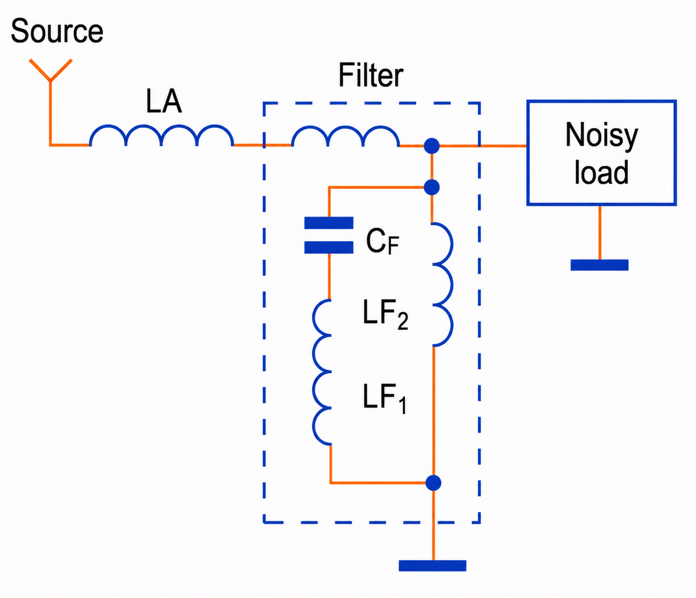
In this filter, we have an additional inductance connected in parallel with the series LC set. This additional inductance reduces the capacitive energy required by the generator, especially during starting.
These passive filters have the main advantage of simplicity and reliability, as well as ease of installation. They are quite efficient when the harmonic distortion rate is less than 5%. However, they have a disadvantage: they only eliminate tuned signals and are not effective over a wider band.
Active Filters
Active filters, or active conditioners as they are also called, are connected in parallel between the harmonic generator and the power supply (see Figure 7).
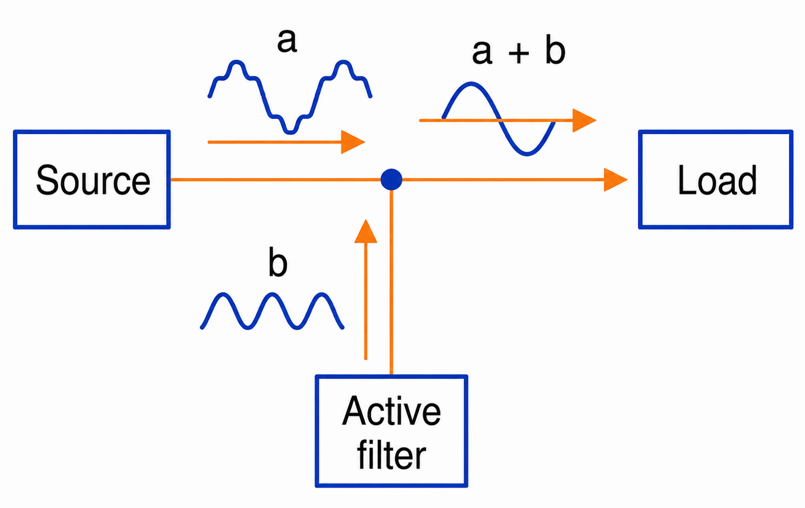
This type of filter monitors the signal phases in real time and, based on this analysis, generates the harmonic spectrum. Using the information contained in this harmonic spectrum, the filter generates a compensation current, which is the difference between the total load current and the fundamental current.
This current (which consists of the sum of the fundamental and harmonic currents) is injected into the circuit, but in phase opposition to cancel out the harmonic signals. The result of the combination of these currents is a pure sinusoidal signal applied to the load. Note that this filter prevents harmonic currents from flowing between the source and the load. Note, then, that other equipment connected to the same source along this path will not be affected by the potential presence of harmonics in the power line.
Active filters are circuits with power semiconductors, typically IGBTs, and are designed to operate in a harmonic range from the second to the twenty-fifth.
Transformers
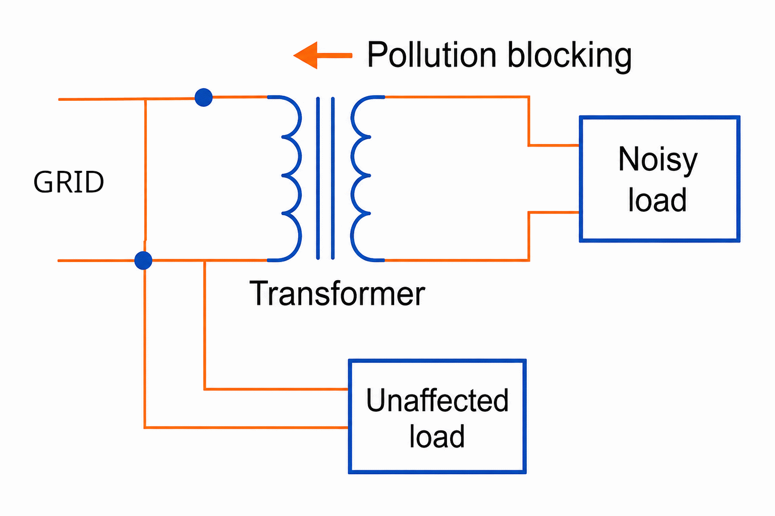
Many installations use transformers to modify voltages and currents, or to create different neutral, isolating sections or providing a higher level of safety.
However, the electrical properties of these components also allow them to be used to confine circuits that power harmonic-generating equipment. A transformer can block the passage of harmonics from one line to another, thus affecting other equipment powered by the same line (see Figure 8).
The way a transformer's windings are connected determines the order in which certain harmonics are blocked. Therefore, we have two possibilities. In the first, shown in Figure 9, a transformer with a delta/wye connection can confine third harmonics and their multiples to the section fed by the secondary’s
.
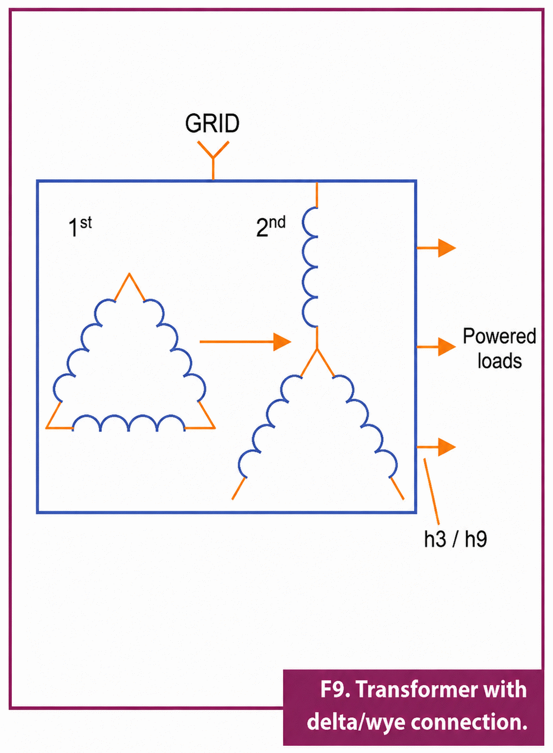
This type of transformer application is especially suitable for powering panels that have equipment with single-phase sources as loads, such as computers, copiers, household appliances, etc. In the case of three-phase loads, where fifth and seventh harmonics predominate, the best solution is to use a transformer with a double secondary, as illustrated in Figure 10.
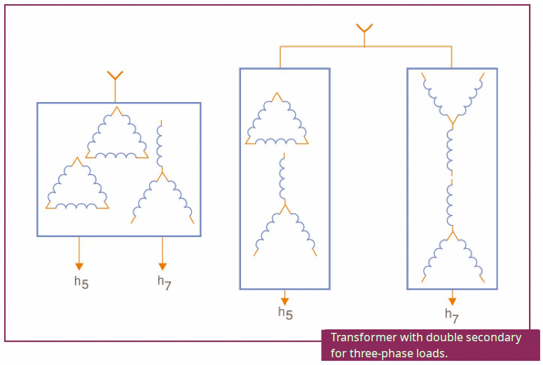
These windings cause a 30-degree phase shift in the voltages, which means that the harmonic currents add algebraically and cancel each other out before the transformer, thus disappearing from the line that feeds the primary. This type of solution must, however, only supply three-phase loads with the same characteristics—that is, those that have the same harmonic spectrum and load the transformer's secondary windings in the same way. This is necessary so that the primary currents, when added together, result in a value as close to zero as possible.
Conclusion
The presence of harmonics in a power line is a problem that is exacerbated by the use of switching devices in most applications. Switched-mode power supplies, thyristors devices that work with fast current switching in frequency inverters, speed controls, and many others generate a large number of harmonics that pollute the power lines, causing various types of problems.
In these two articles, we study how harmonics are generated, what they can cause in an installation, and conclude with some procedures that can be adopted to eliminate them, including the use of filters and transformers.
We also discussed the appropriate selection of cables for installation where harmonics are more frequent, which can cause overheating problems and trip protective devices. We believe this article has been very useful for those who perform electrical installations and maintenance, especially in industries and other locations where these problems can manifest themselves more intensely.


