
ART3846S ART5506
Note: Article published in Electron magazine 06 (1970s)
The reader is certainly familiar with the operating principle of a touch alarm, or simply a touch switch: the small current that flows between the device and your body when you touch it is enough to trigger an SCR, relay, or other device, thus turning on what you want.
This touch alarm, or simply a touch switch, works according to this principle, but it has a feature that most other similar devices do not have and that can be interesting in many cases: timing. This means that once you touch the sensitive element, it turns on whatever you want, but even after you remove your finger from the triggering element, it still remains on, and this for a time interval that you determine, between a few seconds to nearly half an hour.
How can this be useful?
An interesting first application for this circuit is as a home alarm. Simply connect the trigger wire to your home's door lock, and if someone rings during the night, a buzzer or doorbell will sound, alerting you.
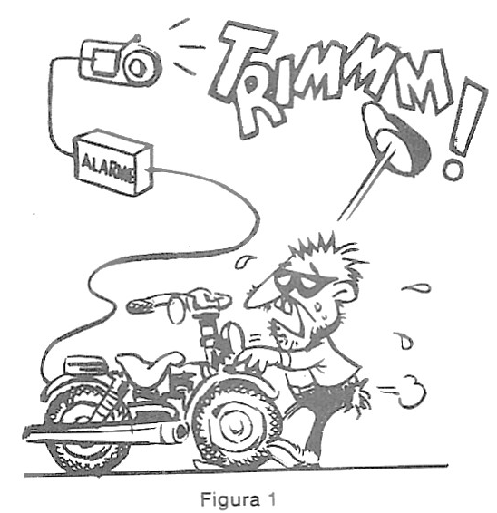
Even if the stranger moves away, the doorbell will still ring for a while, then automatically deactivate. Connecting the sensitive wire to your motorcycle will also protect it from theft, as shown in Figure 1.
Another interesting application is lighting building hallways or stairwells. Touching the sensor that replaces the switch activates the lamp, remaining on for 5 or 10 minutes, as desired, to allow people to circulate. On your porch, this device provides automatic lighting for as long as you need to close the door.
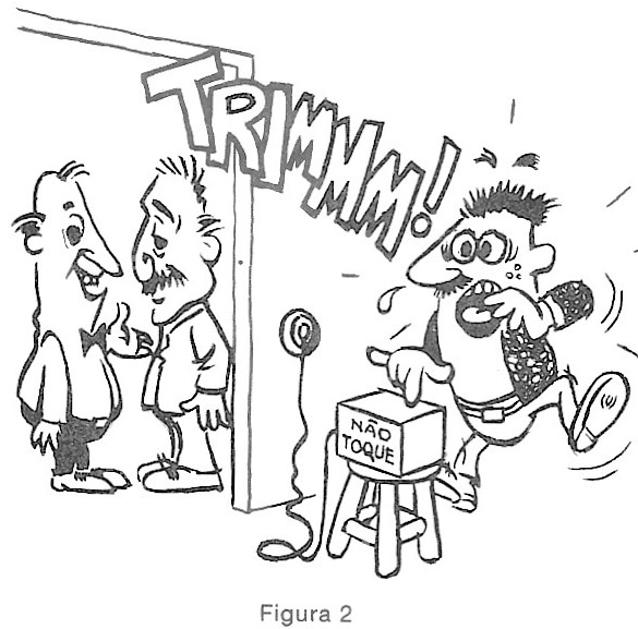
Of course, there is also a recreational application: you can have fun with your friends by installing this switch in a box with a buzzer and wrapping the box with metal foil. Anytime the box is touched, the alarm will sound. This way, you can easily detect the presence of an "onlooker" (fig. 2).
The device's characteristics, given below, give you an idea of its possible applications:
- Supply voltage....... 110/220 V AC
- Maximum load..................... 440 W (110) / 880 W (220V)
- Time range.................. 20 seconds to over half an hour
Basic components....................... 555/MCR106
Based on these characteristics, the reader can immediately decide on its assembly.
How it Works
As mentioned in the introduction, touch switches, like this one, operate by the small current that can flow through a person touching a sensitive element.
Figure 3 shows that if a person touches a sensitive element, such as a plate connected to a potential greater than ground, a current can flow, its intensity being determined by the total resistance of the circuit.
Of course, if the resistance is small and the potential difference between the points is large, the current will be intense and what we call a "shock" will occur.
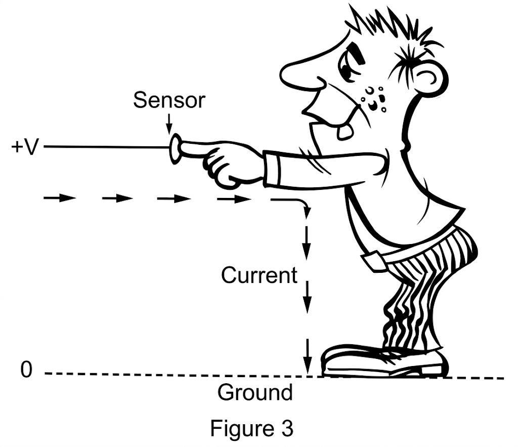
To avoid shock, what is done is to introduce a very high additional resistance into the circuit (above 100,000 ohms), which limits the current to a safe value, that is, low enough to activate the device, but insufficient to cause a shock.
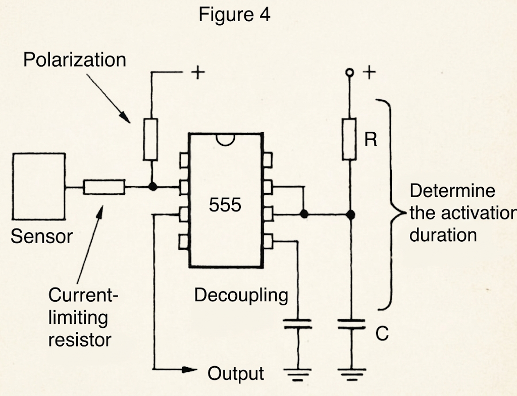
So, our trigger circuit, which is activated as indicated, is represented by the first block in Figure 4. This trigger circuit features a 555 timer that functions as a monostable multivibrator.
In simple terms, we can say that it is a circuit that "turns on" when it receives an electrical impulse (from the sensor) and remains on for a period of time that depends on the values of the components used. In this case, the components are capacitor C1 and resistor R1 in Figure 5, which determine this time. We can modify them if we want to modify the time.
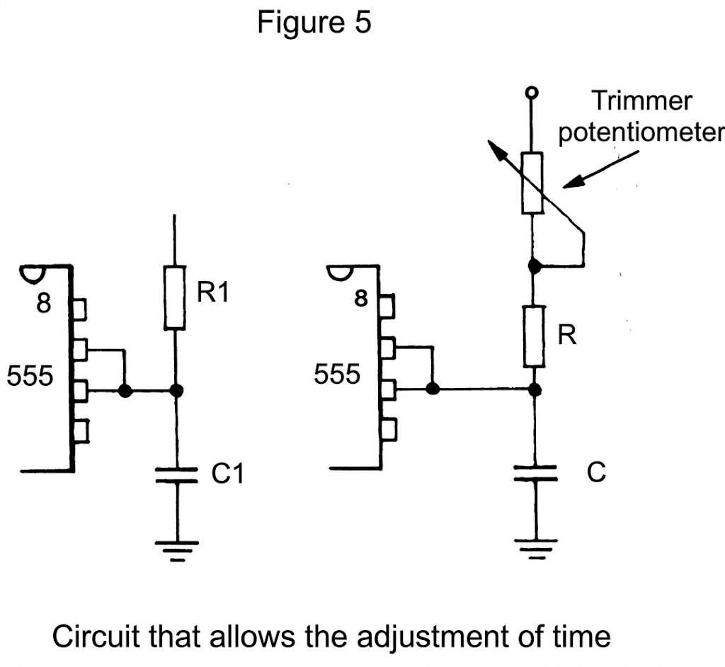
In fact, there is a limit to the highest value of C1 and thus the longest time obtained, which should not exceed much more than half an hour, the same occurring in relation to R1. Once the set time expires, the 555 turns off and waits for a new trigger pulse.
The 555's output is insufficient to directly control a 110 V (220 V) lamp or doorbell. Therefore, we have an additional step in this circuit, which consists of the power module. This basic element is an SCR, a silicon-controlled diode that operates as an on-and-off switch controlled by the 555.
Between the power supply (outlet) and the SCR, we place the lamp or doorbell we want to control and the "gate" is the 555, as shown in Figure 6.
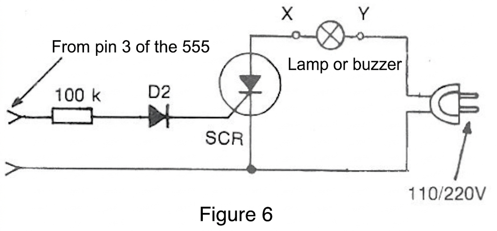
The SCR supports the entire current of the powered device, so the alarm's current capacity depends exclusively on this component. Using an MCR106 SCR, we can control high-power devices, i.e., 440 W on a 110 V network and 880 W on a 220 V network.
To power the 555, a low voltage is required, in the order of 12 to 15 V. This voltage comes from a separate sector of the device in which two resistors form a voltage divider that reduces the 110 V or 220 V to the desired value.
The Material
The basic electronic hardware used in this assembly is readily available, and some parts can even be salvaged from scrap metal. However, depending on the device's intended use, the reader will require some skill to install it in the box and at the operating location.
The following installation options are available:
- Embedded, in the case of lamp controls, when the device must be mounted on a small printed circuit board to be placed where a standard switch is used.
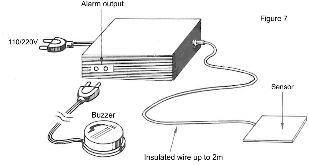
- In a box, in which case the device does not need to be located in the sensor and alarm location, protecting locks, motorcycles, objects, etc. (fig. 7).
- On an object to be protected, in which case it is sufficient to have space available for its placement on a terminal bridge or printed circuit board
Note that the components can be mounted on a printed circuit board or terminal bridge.
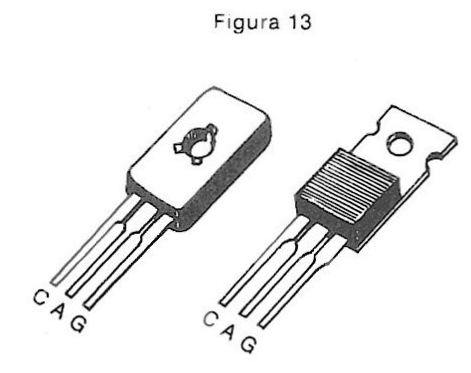
We recommend using a socket for the integrated circuit board (IC) for both board and bridge mounting. The SCRS used can be MCR106, C106, IR106, or others. In the case of the TIC106, a 2kΩ resistor must be connected between the gate and the cathode (C and G). A heat sink must be used for this component.
Resistor R1 is a critical component. It is a 5 W wire-wound resistor, whose value must be chosen depending on whether the network is 110 V or 220 V.
The remaining components are all common. We only note that capacitor C2 determines the timer's activation time, which can range from 2.2 µF (for intervals up to 1 minute) to 470 µF (for times up to half an hour).
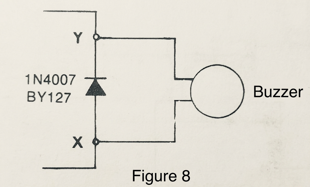
There is one component that allows for options: resistor R3 can be replaced with a 470 kΩ trimmer in series with a 10 kΩ resistor, allowing for time adjustment. For use as an alarm, we suggest using residential buzzers as a warning element. To protect the SCR, a 1N4004 or BY127 diode should be used in parallel, as shown in Figure 8.
Assembly
For both the printed circuit board and bridge versions, inexperienced assemblers are recommended to use a socket for the integrated circuit, and for controlled power ratings above 40W, to use a heatsink for the SCR.
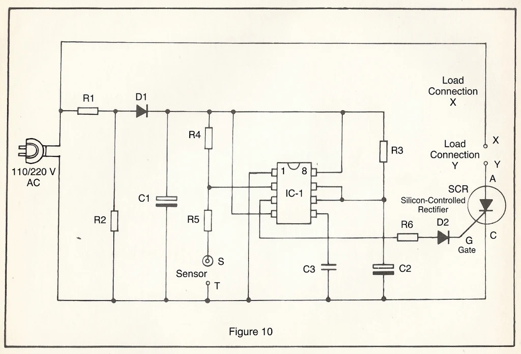
Follow the diagram in the next figure and the component layout for the chosen version.
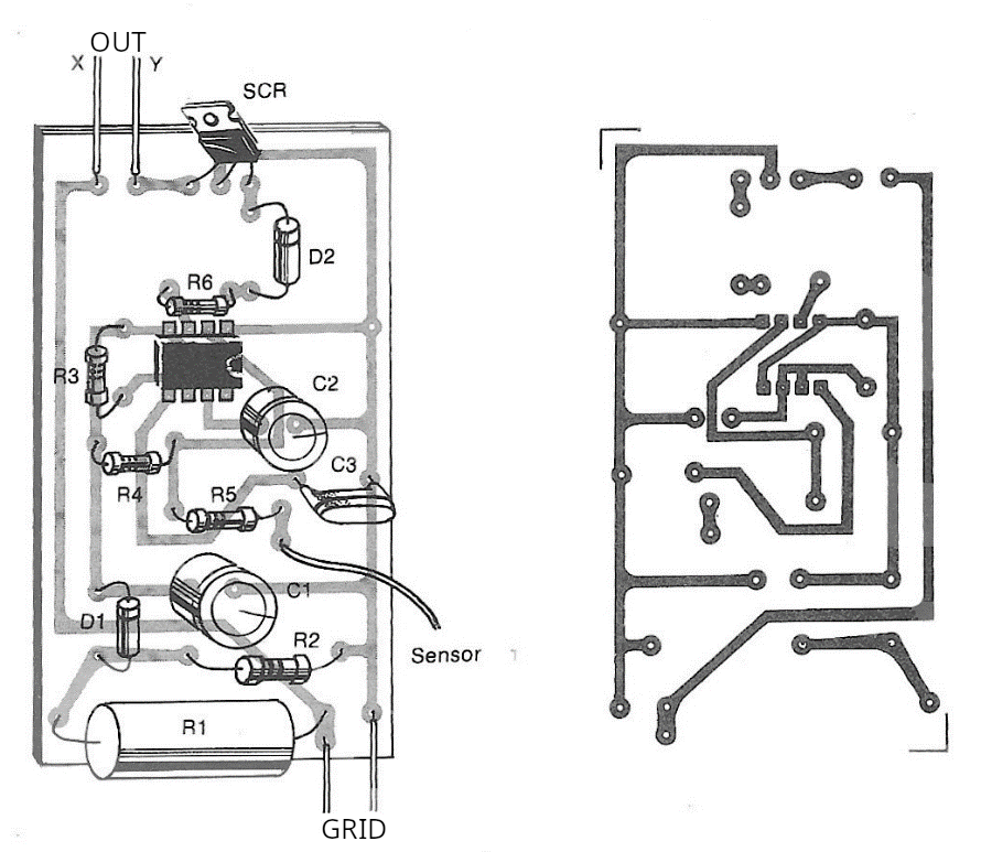
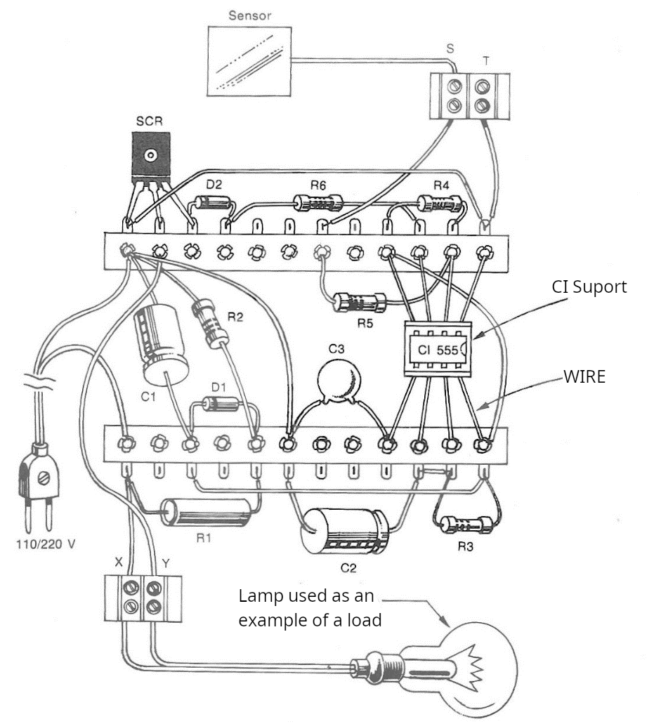
For printed circuit board (shown in figure 11) or terminal bridge (fig. 12), assemblers should take the following precautions:
- Observe the position of the integrated circuit. When soldering this component or its socket, be careful not to leave cold solder joints or spread that could cause short circuits.
Follow the diagram in Figure 10 and the component layout in the chosen version. On a printed circuit board (shown in Figure 11) or a terminal bridge (Fig. 12), the assembler should take the following precautions:
- Observe the position of the integrated circuit. When soldering this component or its socket, be careful not to leave cold solder joints or spread that could cause short circuits.
When soldering the diodes, observe their polarity, as indicated by the stripe.
- Resistor R1 should be soldered so that its body is slightly away from the printed circuit board, or with the long terminals in the bridge version. This component heats up slightly during operation, dissipating the heat generated, in part, by the terminals themselves.
- Electrolytic capacitors have a correct polarity for connection. Please note.
- For the other resistors, simply observe the values by the colored bands. There is no polarity to be observed.
- The load circuit, i.e., alarm, buzzer, lamp, etc., can be placed away from the device. Similarly, if the system is used to illuminate hallways and other areas, the lamp should be placed away.
- The next Figure shows the connection methods for the various devices, thus leaving free terminals for this purpose.
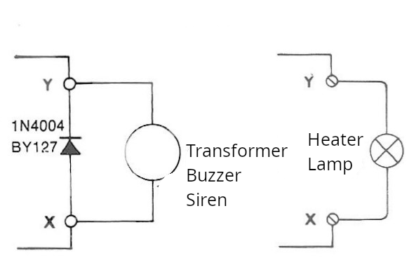
The reader can even place a socket at this point to facilitate connections or simply a screw terminal strip.
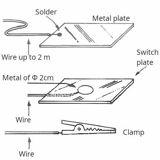
- The sensor used depends on the application, with the following possibilities:
a) For alarms, the sensor wire should be no longer than 2 meters, as it may pick up currents that would affect its stability. This wire will be equipped with a clamp to attach to the protected object. For longer wire lengths, shielded cable can be used.
b) For switches, the sensor is simply a metal plate or plate, whose dimensions can vary from 1 cm on a side to over 30 cm, and these, must be well insulated from any object that makes the various possibilities mentioned.
Testing and Use
Once the device is in perfect working order, connect a load, such as a lamp, buzzer, or siren. Connect the power outlet to the local power supply (110 V or 220 V). The device may start to sound the alarm or turn on the light. Wait for the time specified by capacitor C1 until it stops.
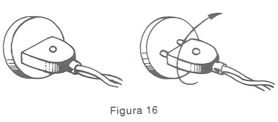
Then, with your fingertip, touch the terminal where the sensor is connected. The alarm should sound. If this does not happen, reverse the position of the outlet, rotating it 180 degrees (half a turn), as shown in the next Figure. Touch the sensor again. The alarm should activate.
The system must be kept activated for a period of time that will depend on the capacitor used. For a 22 µF capacitor, this time is approximately 30 seconds. To avoid having to wait too long, it is advisable to perform operational tests with a small capacitor and, once its operation is verified, replace it with a larger one.
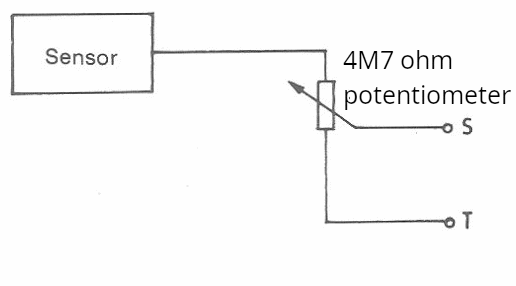
When using it as an alarm, it is important to ensure that the protected element or sensor is perfectly isolated from ground. This is especially true for locks and motorcycles. In some cases, the motorcycle's metal structure, due to its size, can generate a leakage current capable of triggering the alarm. In this case, the reader should add a sensitivity control, as shown in the next Figure, to achieve the correct trigger point.
Material List
CI-1 – 555- Integrated circuit
SCR1 – MCR106, IR106 – C106 or TIC106 for 200V if the network is110V e for 400V if the network is 220V
D1, D2 – 1N4004, 1N4007, BY127 – Silicon diodes
R1 – 10Kohms x 5W – wire resistor – if the network is 110V; 22Kohms x 5W – wire resistor if the network is 220V
R2 – 1K x 1W – resistor (brown, black, red)
R3, R5 – 470 Kohms x 1/8W – resistor (yellow, violet, yellow)
R4 – 2M2 x 1/8W (red, red, green)
R6 – 100Kohms x 1/8W – resistor (brown, black, yellow)
C1 – 100 µF x 16V – Electrolytic capacitor
C2 – 22 µF x 16V – Electrolytic capacitor
C3 – 100 µF – ceramic capacitor
Miscellaneous: mounting box, printed circuit board or terminal bridge, wires, power cable, etc.


