
ART2311 ART1737S
Of course, before describing our system and discussing its advantages, we need to say what a parametric equalizer is. As shown in the curves in Figure 1, this equalizer allows you to change the width of the audio bandwidth, which is applied to the input of an amplifier and then reproduced.
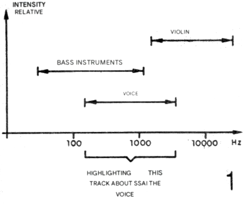
By centering this band in the mid-range, we can have a special enhancement for the human voice and completely modify the timbre of certain instruments. This means that, by interposing this equalizer between a signal source and an amplifier, we can significantly modify the timbre and predominance of certain instruments. See from Figure 2 that an audio signal is composed of the sum of sinusoidal signals of multiple frequencies (Fourier).
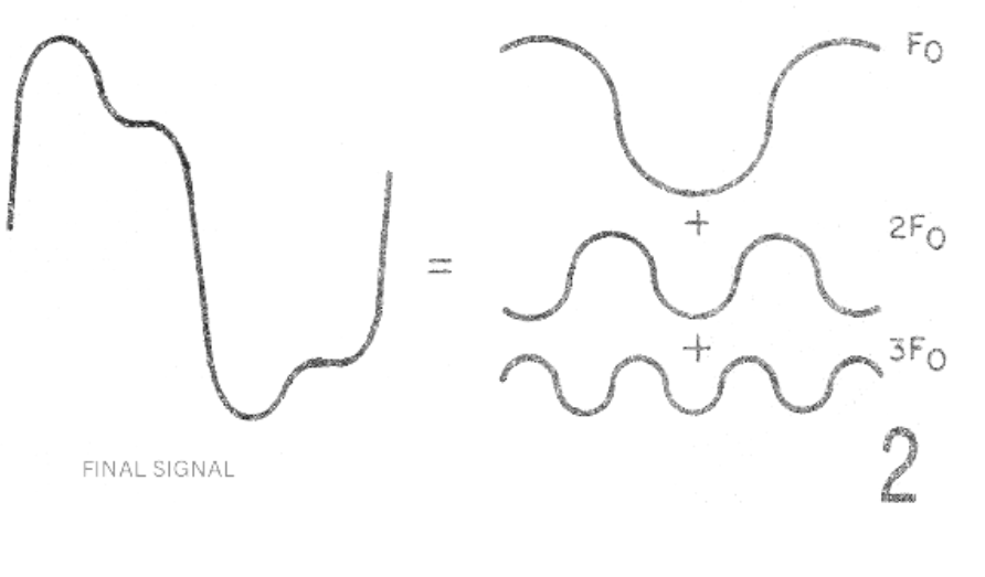
The proportion in which these frequencies appear determines the final waveform of the signal and, therefore, the characteristic known as timbre. By modifying the waveform of this signal by blocking certain harmonics of frequencies lower and higher than a certain value, we also modify the timbre. The equalizer presented allows this to be done.
The components used in the project are common, presenting no difficulty to the assembler, it should only be remembered that, as it is a circuit that operates with low-intensity audio signals, all precautions must be taken regarding the pickup of hum.
CIRCUIT
What we have is an active filter with operational amplifiers (3) whose quality factor (Q), which determines its selectivity, can be altered by adjusting potentiometers, as shown in the schematic diagram in Figure 3.
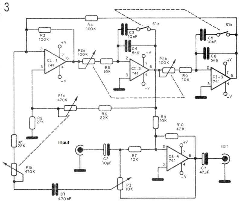
Figure 4 shows the curves obtained for the possible positions of the potentiometers.
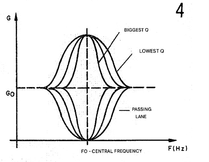
The filters have two capacitor values that allow centering the maximum action frequency (center frequency) at approximately 1000 and 3000 Hz. Of course, if you want to use more capacitors, you can use a 2-pole selector switch with as many positions as there are capacitors, thus obtaining greater versatility for your equalizer. The fourth integrated circuit (IC-4) is used as a buffer for the signal. The power supply should be symmetrical, 12 to 15V, with excellent regulation and filtering to prevent hum in the reproduced signal.
ASSEMBLY
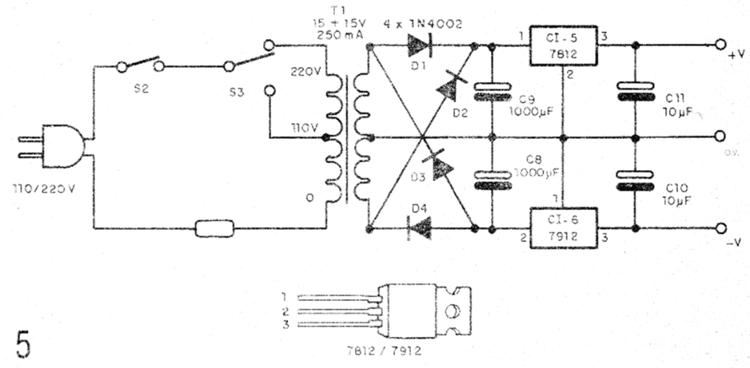
A symmetrical power supply suitable for this circuit is shown in Figure 5.
The printed circuit board for assembly is shown in Figure 6.
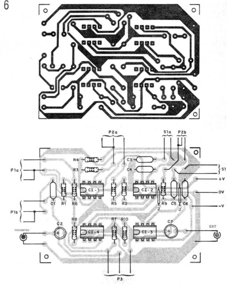
Minor dimensioning adjustments may be necessary depending on the types of components used. The integrated circuits should preferably be mounted in 8-pin DIL sockets. The resistors are all 1/8 W and the electrolytic capacitors are rated for 25 V. The other capacitors can be polyester or ceramic. Potentiometers P1 and P2 are dual linear potentiometers, either rotary or sliding type, depending on the enclosure and panel designed by the assembler.
P3 is a simple linear potentiometer and switch S1 is a 2-pole x 2-position switch, used in this case as a double switch. For the signal input and output, shielded wires and appropriate jacks should be used, according to the signal source and amplifier input. The input impedance of the circuit is on the order of 1-ohm, and the sensitivity is around 100 mV. At the output, we obtain a signal of approximately 500 mV with low impedance (150 ohms), which can easily drive the input of most amplifiers without problems.
For the power supply, the regulators can be fitted with small heat sinks, since the current supplied is low. Note the different arrangements for the terminals of the 7812 and 7912 regulators next to the diagram. The transformer can have secondary currents starting from 250 mA.
TESTING AND USE
Interlace the equalizer between a signal source (preamplifier, tape deck, turntable, etc.) and the input of an audio amplifier. Turn on the audio amplifier at half volume and the signal source. Activate the equalizer and adjust the controls. P1 and P2 adjust the width of the curve, while P3 adjusts the depth of the adjustment. S1 is used to modify the positioning of the center frequency on the equalization graph. With S1 open, the centering will be in higher-pitched sounds, and with S1 closed, the centering will be in mid-range sounds. To use, simply adjust the controls to obtain the desired reproduction. If you have an oscilloscope available, you can easily measure the operating characteristics of all the controls, working with a graph of real values, as suggested in Figure 7.
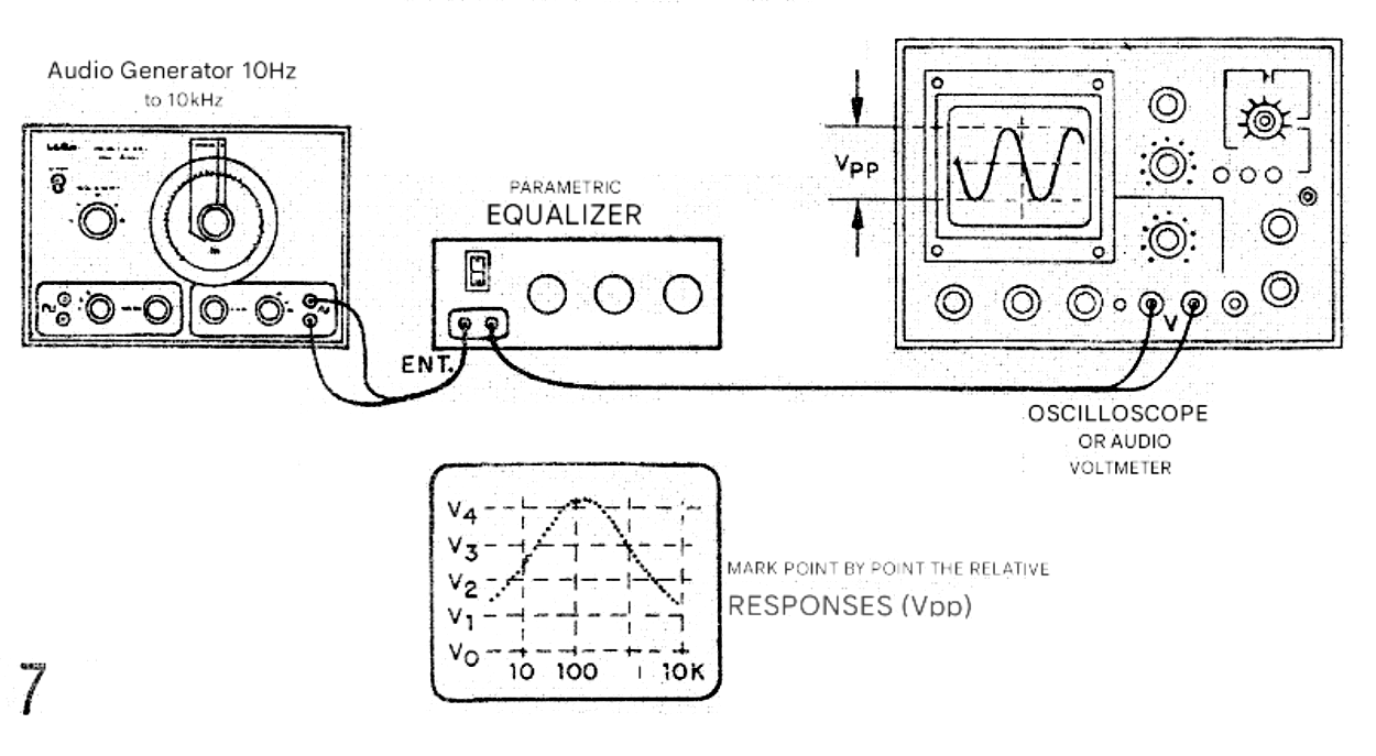
It shows how to connect the oscilloscope and a signal generator to plot the curve. By scanning the amplifier's playback range, note the relative strengths of the audio signals at the output using an audio voltmeter.
LIST OF MATERIALS
IC-1 to IC-4 - pA741 - operational amplifiers
P1 - 100 kΩ - dual linear potentiometer
P2 - 47 kΩ - dual linear potentiometer
P3 - 10 kΩ - single linear potentiometer
S1 - double switch or 2 x 2 switch
R1, R6 – 22 kΩ - resistors (red, red, orange)
R2 - 27 kΩ - resistor (red, violet, orange)
R3, R4 - 100 kΩ - resistors (brown, black, yellow)
R5, R7, R8, R9 – 10 kΩ – resistors (brown, black, orange)
R10 – 47 kΩ - resistor (yellow, violet, orange)
C1 – 470 nF - ceramic or polyester capacitor
C2 – 10 uF - electrolytic capacitor
C3, C5 – 10 nF - ceramic or polyester capacitors
C4, C6 - 5n6 - Ceramic or polyester capacitors
C7 - 47 uF - electrolytic capacitor
Power supply:
T1 - 15+15 V x 250 mA - transformer with primary winding according to the local mains voltage
IC-5 - 7812 - integrated voltage regulator
IC-6 - 7912 - integrated voltage regulator
D1 to D4 - 1N4002 or equivalent rectifier diodes
C8, C9 – 1000 uF - electrolytic capacitors
C10, IC1 – 10 uF - electrolytic capacitors
S2 - simple switch
S3 - Voltage switch 110/220 V
F1 – 1 A - fuse
Miscellaneous: printed circuit board, mounting box, power cable, knobs for the potentiometers, input and output jacks, sockets for the integrated circuits, wires, solder, fuse holder, heat sinks for the voltage regulators, etc.


