
ART743S FC ART2235 (A)
While some technicians use a mechanical stethoscope, that method relies on acoustic sound waves. The project presented here is more efficient: it captures the mechanical vibration itself. Using a common ceramic capacitor as a high-sensitivity transducer, this fully portable device amplifies sub-surface noises and reproduces them with excellent volume in a loudspeaker or headphones.
Strong or strange vibrations, knocks, or other problems that occur with machines, motors, or vehicles are difficult to detect "by ear" due to the existence of other noises, the normal operating noises, that mask them. One process used is based on a stethoscope, but this type of resource is not very appropriate, as it is not based on capturing the vibration itself, but on the sound, it produces.
A more efficient way to detect knocks or vibrations uses a inexpensive and even novel transducer for some who are unfamiliar with its properties: a ceramic disc capacitor is the transducer, since this component has a dielectric with high sensitivity to vibrations, generating a signal under these conditions that can be amplified and reproduced. The device we propose uses this transducer and has 3 integrated circuits that guarantee excellent performance.
Among the suggested applications are the following:
• Detection of vibrations or knocks in industrial machines
• Detection of noise in car exhaust systems
• Detection of noise and knocks in engines
• Verification of the movement of mechanisms or vehicles
• Verification of noise transmission in structures
The basic characteristics of the device are:
• Supply voltage: 6 to 9 V
• Number of integrated circuits:
• Quiet current: 5 mA (typ)
• Amplification gain 70 dB (typ)
HOW IT WORKS
The heart of our device is the sensor, which consists of a disc-type ceramic capacitor that, as shown in Figure 1, has a structure that allows the detection of beats or vibrations.
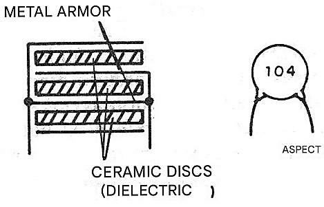
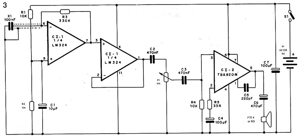
A bump or vibration significantly alters the dielectric, reducing or increasing its thickness, and thus generating a signal that appears between the plates. This signal is applied to the inverting input of one of the four operational amplifiers in the LM324 integrated circuit. This first amplifier operates with a gain of approximately 30 times (given by the feedback resistor R3, which can be changed), and its signal is fed to the input of a second operational amplifier that operates with unity gain (voltage follower).
Under these conditions, we have a very high input impedance and a very low output impedance, which allows the excitation of an audio amplifier without problems. The audio amplifier's excitation signal first passes through a volume control.
The suggested audio amplifier is the TBA820M, but if it is unavailable, equivalents such as the TBA820S or TBA820 (different pinout) or even the LM380 or LM386, which are also quite popular and all operate with voltages in the range of 6 to 12 V, can be used.
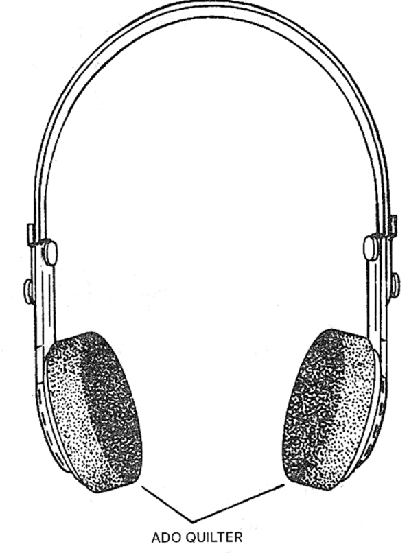
At the output, we use a small 4 or 8-ohm speaker, but if the device is used in environments with a high noise level, we suggest adding a headphone output. The headphones can be of the type used in portable sound systems, with low impedance, or if the location is subject to very high noise levels, we suggest the padded type as shown in Figure 2.
Power can be supplied with voltages in the range of 6 to 12 V.
We suggest using 4 (6V) batteries or a (9V) battery, although in the case of the battery, besides a smaller volume for assembly, we have reduced durability due to the current consumption of the unit.
ASSEMBLY
Figure 3 shows the complete diagram of this sensor.
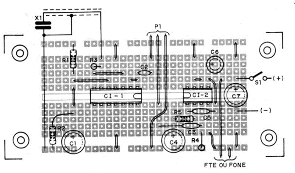
The arrangement of the components, based on a universal printed circuit board with a breadboard layout, is shown in Figure 4.
The sensor is nothing more than a 100 nF (10⁴ or 0.1) ceramic capacitor that must be connected to the device using a shielded cable up to 2 meters long. At the junction of the cable and capacitor, a little epoxy glue can be used for protection.
The suggested integrated circuit is the LM324 or any dual or quad operational amplifier with characteristics similar to the 741. In fact, 741-type operational amplifiers with a 9V supply voltage can also be used with a redesign of the printed circuit board.
For the integrated circuits, we suggest using DIL sockets according to the pinouts. The resistors are all 1/8 or 1/4W with 10% or 20% tolerance, and the electrolytic capacitors should have working voltages above 9V. The other capacitors can be ceramic or polyester, and their values are not critical, especially in the case of C2 and C3. The volume potentiometer P1 can incorporate the general switch S1. The assembly can be installed in a box, as shown in Figure 5.
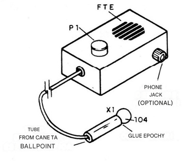
The battery holder will be fixed by means of a clamp or pad made from a piece of foam. The same applies if a battery is used. For the speaker, we suggest using a 5 cm unit with 8 ohms impedance, quite common in radios, which can be easily installed in the suggested box. The headphone jack is of the closed-circuit type and its connection is shown in Figure 6.
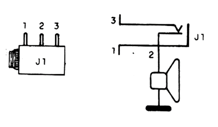
With this type of connection, when the headphone plug is inserted, the speaker is automatically switched off.
TESTING AND USE
To test, simply turn on the unit and increase the volume. Tapping the X1 sensor with your fingers or a metal object should reproduce the sound of the tap. To use, you must place the sensor against the object or mechanism that may be vibrating. If there is strong vibration or any kind of tap, it will be reproduced by the speaker or headphones.
An interesting possibility, given the low cost of the sensor, is to glue 100 nF ceramic capacitors with epoxy to the machines you want to monitor and simply connect the device using two clips, whenever you want to monitor some noise or perform a check. The reader will observe that ambient noises are not captured, but only those transmitted by direct contact with the X1 sensor.
This ensures that the captured signal comes from the vibration transmitted directly by the mechanism to the sensor.
LIST OF MATERIALS
IC-1 - LM324 or equivalent - quad operational amplifier
IC-2 - TBA820 M - audio amplifier
X1 – 100 nF - ceramic sensor capacitor - see text
S1 - Simple switch
B1 - 6 or 9 V (4 batteries or battery pack)
FTE - 4 or 8-ohm x 5cm speaker
Pl – 10 k ohms - potentiometer (log with switch – S1)
R1, R2, R4 – 10 k ohms - resistors (brown, black, orange)
R3 - 330 or 390 ohms - resistor (orange, orange, yellow) or (orange, white, yellow)
R5 – 33 ohms - resistor (orange, orange, black)
C1 – 100 uF - electrolytic capacitor
C2, C3 – 470 nF (473 or 0.47) - ceramic or polyester capacitors
C4, C7 – 100 uF - electrolytic capacitors
C6 – 470 nF - electrolytic capacitor
C5 – 220 pF - ceramic capacitor
Miscellaneous: universal printed circuit board, mounting box, battery holder or connector, integrated circuit holder, shielded wire, closed-circuit jack for headphones, etc.


