Obs. This project after be published in a Brazilian Magazine was included in my book CMOS Projects and Experiments (Newnes 1999)
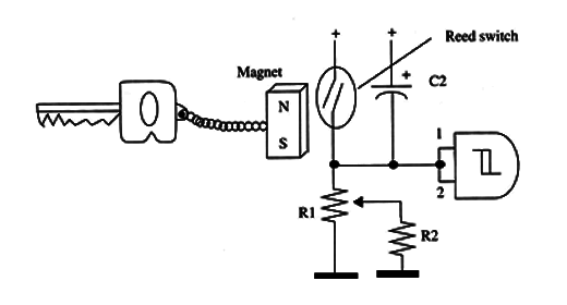
To set a new time delay and turn a front door light on during the set time, you need to use a small hole through which a secret push-button can be pressed. Alternatively, you can also replace the push-button with a reed switch that is activated by a small magnet attached to your keyholder as suggested in Fig.1

The circuit can be used with common alarms and powered from the ac power line or battery (the same one that powers the alarm).
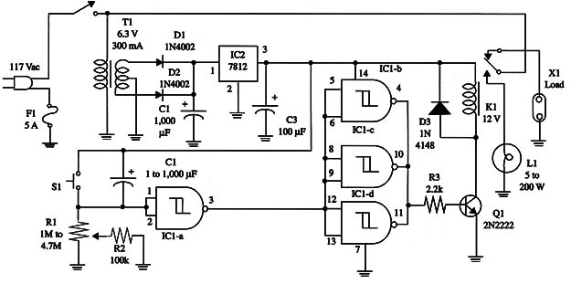
Operation is as follows. When S1 is closed, power is on, and C2 begins to charge through R1 and R2. R1 adjusts the time delay. As soon a Vp is reached in pin 2 (ICl-a), its output goes high, and ICl-b, c, and d outputs go low, turning off the relay.
During C2 charging, the relay is on, and the lamp glows. After the programmed time delay, the relay turns off, and the alarm’s power comes on.
To set a new time delay (when you come back to home), S2 should be pressed. Then, C2 begins a new charge, and the alarm’s power supply is cut off during the adjusted time delay.
A schematic diagram of the timer is given in Fig. 2.

Proper positioning of the polarized components (diodes, electrolytic capacitors, and transistor) must be observed.
In the basic project, we used a mini DPDT relay (12 V, 43 mA, Radio Shack 273-1365) that could be mounted on a solderless board or universal printed circuit board.
If you’re using another type of relay, depending on the terminal positions, the layout must be altered.
Heavy-duty relays also can be used, but if they have coils rated in the range of 100 mA to 500 mA, transistor Q1 must be replaced with a Darlington or an NPN power transistor such as the TIP31 or TIP110.
The external battery should be connected to the power supply via D4 for ac line failure.
S2 should be installed in a secret place. If you’re using a reed switch as S2, it can be installed under a thin plastic panel to facilitate the magnet’s action.
IC1 - 4093 CMOS integrated circuit
IC2 - 7812 voltage regulator IC
Q1 - 2N2222 NPN general purpose silicon transistor
D1, D2, D3 - 1N4002 silicon rectifiers (50 V, 1 A)
K1 - 12 V, 100 mA relay, Radio Shack 275-249 or equivalent
T1 - Transformer: 12.6 V, 450 mA secondary CT, Radio Shack 27 3-1365 or equivalent, primary 117 Vac
D4 - 1N4002 or equivalent silicon rectifier (see text)
S1 - SPST toggle or slide switch
S2 - SPST reed switch or momentary switch
F1 - 5 A fuse and holder
R1 - 1,000,000 ohm to 4,700,000 ohm - potentiometer
R2 - 100,000 ohm, 1/4 W, 5% - resistor
R3 - 2,200 ohm, 1/4 W, 5% - resistor
C1 - 1,000 µF, 25 WVDC - electrolytic capacitor
C2 - 100 µF to 1,000 µF, 16 WVDC - electrolytic capacitor
C3 - 100 µF, 16 WVDC - electrolytic capacitor


