Sensors, in most types, consist of transducers which convert a physical magnitude into an electric current or voltage. One type of sensor that meets a wide range of electronics applications, particularly in automation, IoT and wearables, is the physical force sensor which can be presented in two round FSR (Force Sensing Resistors) and Ribbon configurations.
Their range of applications is huge, as we will see, and they can be found easily, for example at Mouser Electronics, highlighting the Adafruit types which we will provide the links. Basically they consist of a sensor that when receiving a physical pressure, for example, the pressure of the fingers, changes its electrical resistance.
So let's look at the common types:
FSR
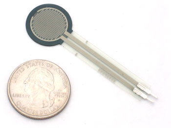
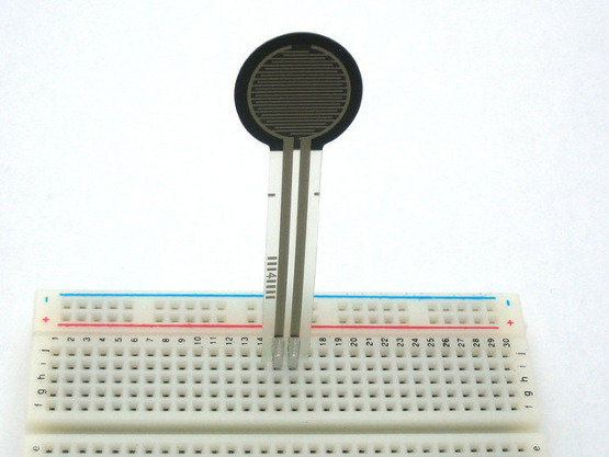
FSR is the acronym for force sensitive resistor. In Figure 1, we have a common type, Interlink 402 which is sold through Adafruit at Mouser Electronics. Visit https://learn.adafruit.com/force-sensitive-resistor-fsr/overview for more information.
In Figure 1, we have the aspect of this sensor that can be directly embedded on a breadboard to develop a microcontroller shield (Arduino, for example).
In Figure 2, we have the way this sensor is built. Basically, it consists of a resistor whose resistance changes with the mechanical pressure. Electrically, we can compare it to an LDR (Light Dependent Resistor) where resistance changes with the light, or an NTC (Negative Temperature Coefficient) where resistance changes with the temperature. The circuits, they use in an interface, are similar and in some cases may even be the same depending only on the range of pressures covered.
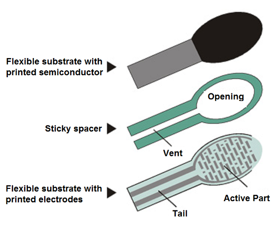
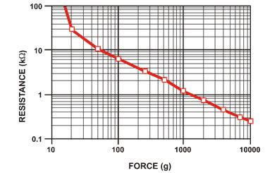
In this type of sensor, the resistance decreases with the increasing pressure, i.e., force per area unit. The accuracy is around 10% which allows its use in simple projects involving the measurement of forces. On this same website, we have a collaborator article which teaches how to assemble an experimental microcontrolled scale using a sensor of this type.
A common type sensor of this kind such as the Interlink 402 has a resistance on the order of 100 k without any pressure and this pressure drops to 200 ohms with a pressure of 100 Newtons which is the recommended maximum and corresponds to 20 pounds distributed per area of 0.125 square inches.
The recommended current in the operating range is less than 1 A and its dimensions are 12.5 mm active diameter and a thickness of just 0.02 inches.
In Figure 3, we have its characteristic curve.
In Figure 4, on the Adafruit website, we have a simple way to test and verify the operation of such a sensor.
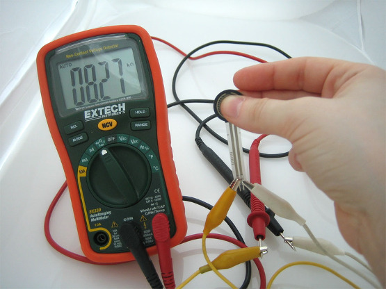
Figure 5 shows the immediate way of inserting an FSR sensor into a breadboard to develop a circuit.
In Figure 6, we have an experimental circuit of a force indicator (which can be used in a game, for example) and which uses a scale of 4 LEDs (Light Emitting Diode). Of course, a more accurate version can be made with one LM3914 or even two 4093. Several bargraph circuits or dot indicator or movable bar are available on the website.
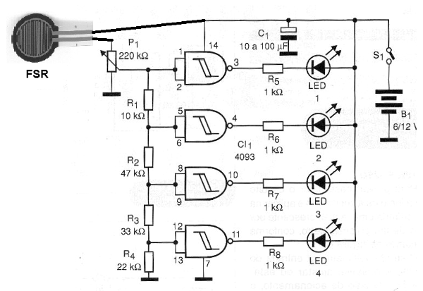
The setting trimpot value depends on the sensed pressure range and can typically be between 10k and 220k.
Ribbon Sensors
These resistive sensors are true electronic touch potentiometers, as their resistance depends on where you press the tape. In Figure 7, we have a sensor of this type by Adafruit that can be purchased from Mouser Electronics.
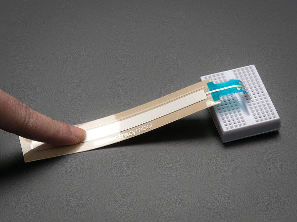
This sensor is manufactured by Spectra Symbol and sold by Mouser Electronics. See more at: https://www.mouser.com/Search/Refine.aspx?Keyword=Spectra+symbol
For the type shown in the photo, the use is very simple. The component has a resistance of 10 k between the extreme pins (as in a potentiometer, it has three terminals). The resistance of the middle pin to the extreme pins depends on the point of the tape we touch, that is, our finger is the potentiometer cursor. When no pressure is placed on the component the middle pin becomes floating with a resistance of 100 k relative to the others.
To use, ground one of the end pins via a 10k resistor in series. The other side is connected to a Vcc source according to the circuit. The source can be 3, 5 V, etc, depending on the microcontroller or even the digital logic or circuit (comparators, for example) which must be controlled.
The voltage read at the cursor will vary between 1/3 and 2; 3 Vcc. It is not recommended to simultaneously turn on the ground and the Vcc ends.
More information about these sensors can be obtained on the Adafruit website.
Application Suggestions
Surely imaginative readers who are looking for a good design for a Superior Education Project, a new product, or even for recreation using their Arduino, common logic or analog circuits may have many ideas. In IoT, wearable and others, for example, there are many suggestions, some even funny, ideal for fairs and demonstrations. For example:
- How about putting a linear sensor on the back of a pair of “smart” pants? Every time you sit down you can light up a red LED on your cap wirelessly. This is an ideal pair of pants for vigilantes who should stand up. If you sit down, the alarm sounds and the LED lights up!
- In a robot or vehicle such a sensor on the front can have intelligent functions. If the obstacle is light, it simply pushes it, but if the effort is greater than a certain programmed value, it activates a stop or reverse circuit.
- In an IoT application it can report the presence of people or objects by weight, and a selective criterion which determines the circuit action according to the weight can be used.
Anyway, there are no limits to what can be done. How about creating a good project and sending it to us for publication?


