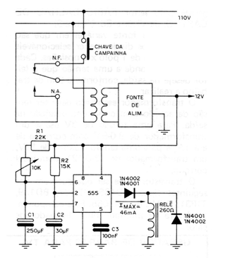
The circuit found in a 1983 publication is shown in the figure. Taking advantage of the capacitor's characteristic of not allowing sudden variations in voltage between its terminals, when the bell is touched, point 2 is connected to earth and the timer goes off. At this moment, the relay NO contact is activated, and the circuit will work, even after the switch is released. When point 3 returns to level 0, the entire circuit is deactivated, ready for a new cycle. The 12 V power supply can control an electronic bell instead of the conventional one. Important in this circuit is that the R2 / C2 branch must have a time constant greater than the voltage rise of the source, that is, when the source reaches 12 V, pin 2 must have less than 4 V (this occurs in a time approximately 1.8 seconds, which is more than enough). In the interval from one melody to another (musical bell), or waiting, capacitor C2 must discharge itself, and this occurs through the internal circuit of the 555 (in approximately 3.5 seconds). If you want to change this time, a 680 R x 1 / 2W resistor is placed in parallel with the source, when the time will drop to approximately 1.4 s. The R2 x C2 value cannot be greater than the timer active time.