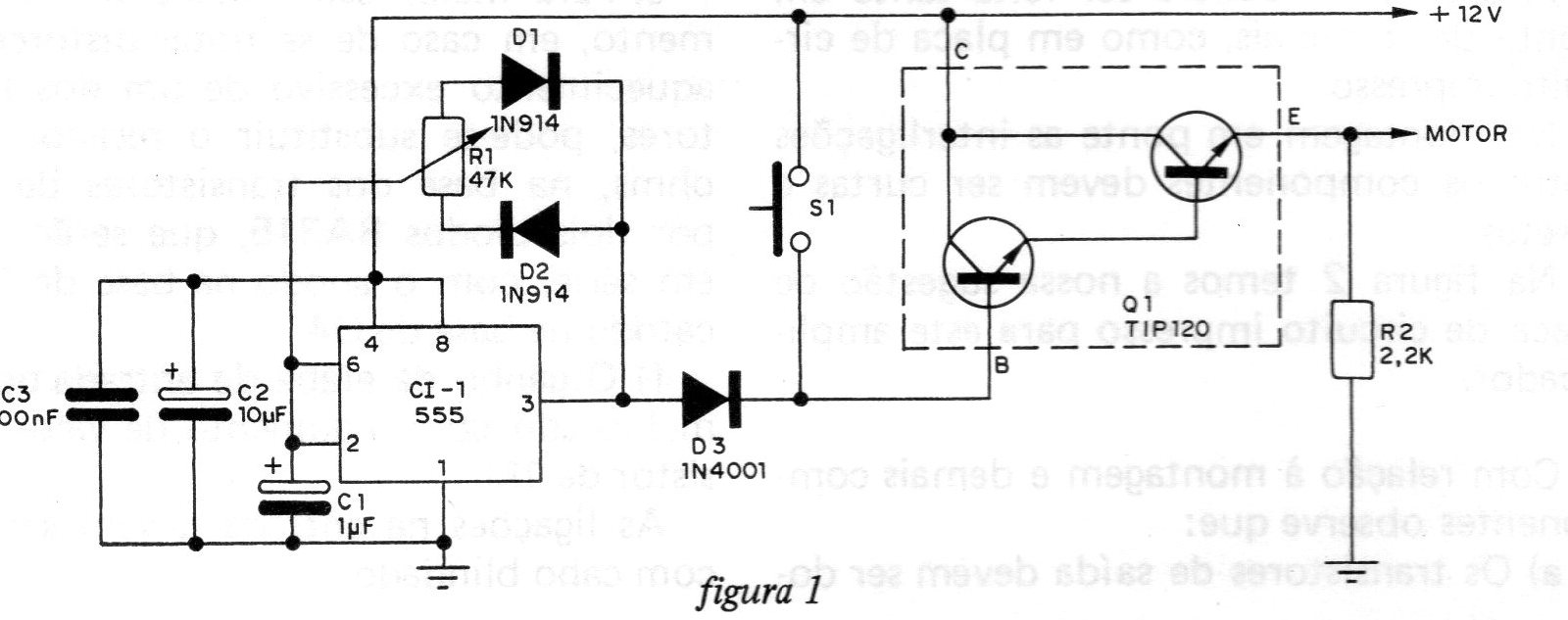
This control, from a 1982 documentation, uses an integrated circuit and a Darlington transistor, as shown in the figure. The operation of the circuit is as follows: the basis of the control is a pulse generator, in which the resistor R1 controls its duration and separation. As we can see, both the charge and discharge of capacitor C1 are controlled by R1. Diodes D1 and D2 also control this charge and discharge. Thus, when the cursor of R1 is in the central position, the charge of C1 will be equal to its discharge. However, when the cursor of R1 is on the side of D1, capacitor C1 discharges quickly and charges more slowly. The reverse situation occurs when the cursor of R1 is on the side of D2. The discharge is slower and the loading faster. The pulses present on pin 3 of Cl1 are amplified by transistor Q1, and then applied to the car's engine. If the pulses have a short duration and a large spacing, the speed will be small, and if they have a long duration and a small spacing, the speed will be greater. In case of quick start, S1 is normally used.