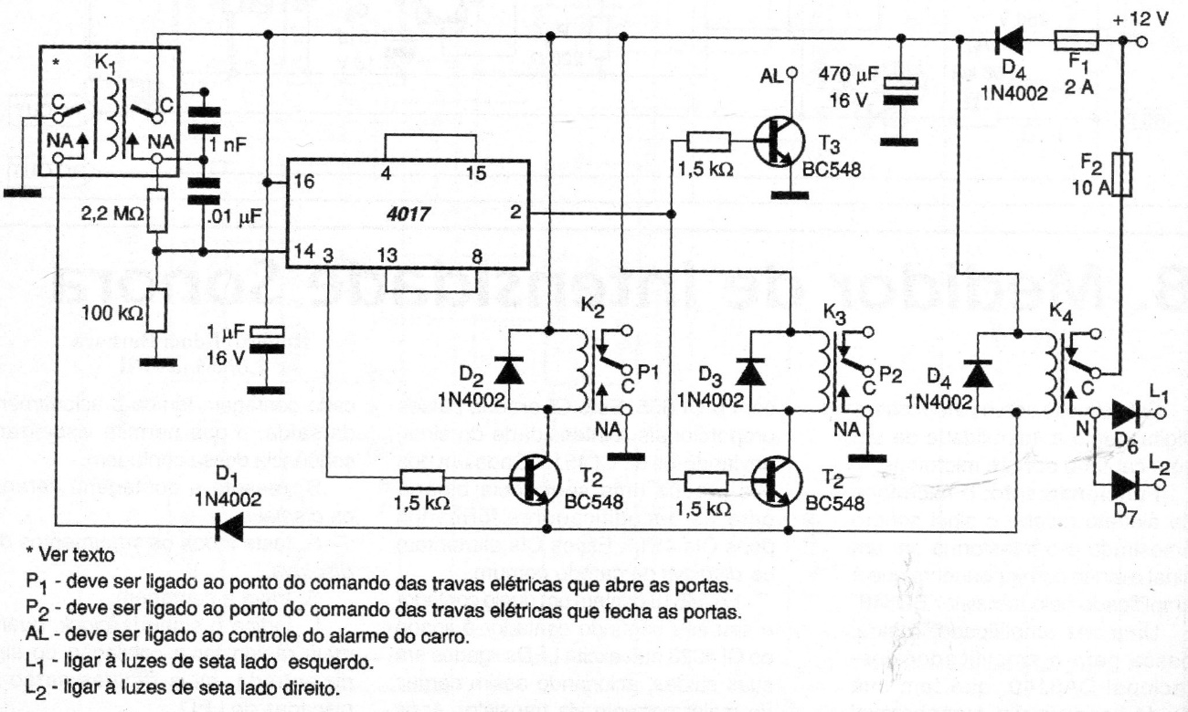
The circuit we have just described has been mounted in the car of the author of the project for about a year, without any problems (Uno Mille Fire with original electrical locks). The project is from 2003. It is an interface to control the doors and the alarm of the car through a remote control. The remote control used is a TRA1 or RCA1, of these that are used in garage gates, however any type of remote control that works with the 12 V of the car battery can be used. The only necessary modification is to replace the relay of a reversible contact on the remote-control receiver with one of two reversible contacts. In the diagram, in the square marked K1, we have the remote-control relay. Transistor T3 controls the activation of the alarm that only occurs when the doors are locked. This alarm is inhibited if T3 keeps it connected to the negative of the supply. When the doors are locked, the transistor is turned off and the alarm is armed. Of course, any other type of alarm can be used with the necessary modifications to the circuit. Relays K2, K3 and K4 used in the circuit are 12 V with a reversible contact, except the relay K1 of the remote control which is 12 V with two reversible contacts.