This transmitter is modulated by & variable capacitance diode (varicap) and can transmit a high-quality audio signal up to several miles.
Features
Power supply between 6 and 12 V when using the 2N2218 transistor
Power supply between 12 and 18 V when using the 2N3553 transistor
High output power: 1 W with the 2N2218, 2 W with the 2N2553
Current drain between 200 and 500 mA
Wide frequency band: between 60 and 120 MHz
Varicap modulation
High-power FM transmitters must not be used in cities or other places where they might interfere with other communication systems. However, in sparsely populated areas such as farms or campgrounds, a high-power FM transmitter can be used successfully under limited conditions.
The transmitter described here can be used as an experimental radio station in such places. You can produce your own radio programs for clubs, camping trips, or just for listening at various locations on a farm.
Our project consists of a two-transistor, high-power transmitter with a push-pull output stage. It can be powered from 6 to 18 V supplies, depending on the version. This transmitter can deliver 1 to 2 watts of signal to an antenna, which is enough to cover distances up to several miles.
The principal characteristic of this project is the use of a variable capacitance diode (varicap) in the modulation circuit. Using this device, the circuit can produce a high-quality signal, which is important for use as an experimental broadcast station.
The circuit is designed to use an electret microphone, but the reader can use other signals sources, including the mixer stage described in other project in this site. The circuit generates a high-power output, so it is important that the reader understand and observe laws limiting or prohibiting the operation of these devices.
How It Works
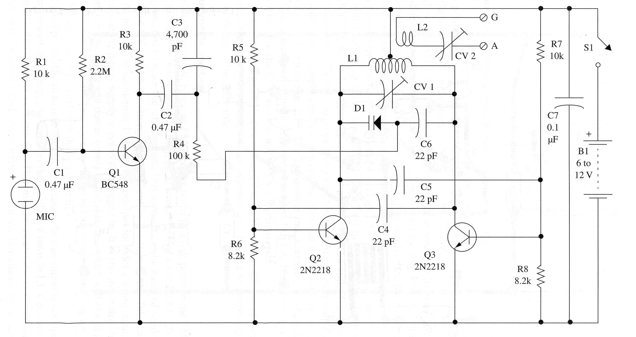
The core of the circuit is a high-frequency oscillator that uses two transistors in a push-pull configuration. The transistors are wired to a center-tapped coil, providing the feedback circuit.
The coil, with a trimmer capacitor and a varicap, determine the operational frequency. The trimmer must be adjusted to a central frequency, at a free point in the FM band.
The feedback signal to Q2 is picked up from the collector of Q3 via C4, and the feedback signal to Q3 is picked up from Q2 via C5. The transistors are biased by R5, R6, R7, and R8. The values of the resistors vary according to the transistor used in the circuit. For the 2N3553, resistors R6 and R7 must be reduced to 6,800 ohm or 5,600 ohm, and R6 and R7 to 4,700 or 3,900 ohm.
The signal produced by the circuit is coupled to the antenna by a second coil interlaced with Ll, the oscillator coil. An electret microphone picks up the audio signal and applies it to the base of an NPN general-purpose transistor for amplification. The amplified signal is then applied to the varicap via R4.
It is useful to discuss how the varicap diode functions in this circuit, as the same principle is applied in many other applications. Any diode acts as a varicap when it is reverse biased. What happens is that, when the junction of a common diode is reverse biased as shown in Fig. 1, the charge carriers are separated, and a dielectric region forms between them. This means that the device can be considered to be a capacitor.
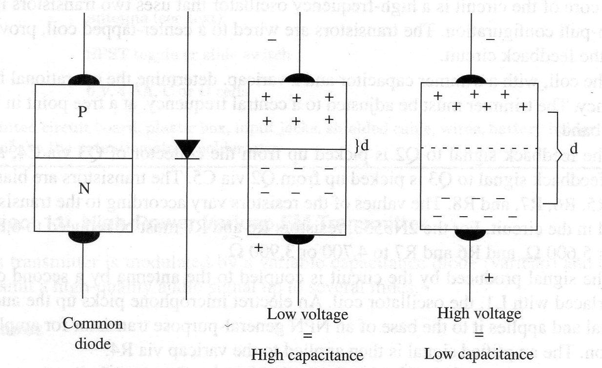
However, the separation between the charge carriers depends on the reversed applied voltage, so we can control this virtual capacitor”s capacitance by changing the applied voltage. Higher voltage increases the charge separation and so decreases the capacitance.
A common silicon diode such as the lN4002 acts as a varicap-but not a good one, because the achieved capacitance range is narrow. If you use a common diode in a circuit like the one described here, it will operate, but only when using strong audio signals.
And yet, there are special diodes with large junction surfaces that can combine a wide range of capacitances With a low range of reverse voltages. Those diodes are named varicaps and can be found in radio receivers, TV sets, and other tuning circuits.
Figure 2 shows how a varicap can be used to tune a resonant circuit using a potentiometer or trimmer potentiometer. The varicap, in series with a common capacitor, replaces the variable capacitor in a common LC resonant circuit. The coil and the varicap basically determine the resonant frequency.
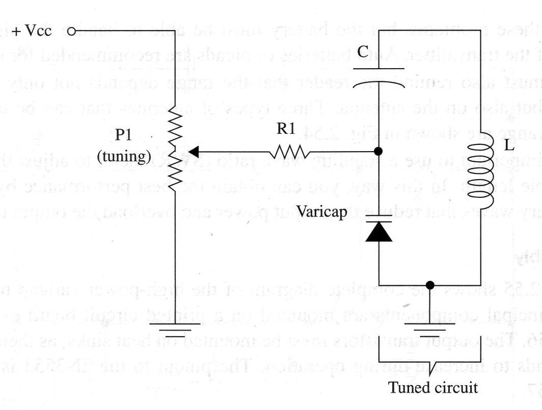
Normally, C is chosen so as to avoid influencing the net capacitance presented by itself and the varicap. This means a value many times higher than the mean capacitance presented by the varicap.
The voltage that changes the varicap capacitance is applied via R, coming from a trimmer or common potentiometer, so the resulting capacitance and the circuit resonant frequency can be changed by the trimmer or common potentiometer.
Many FM, TV, and communication receivers are tuned by such circuits.
To generate the modulation from an audio signal, it is enough to apply this signal to the varicap. The voltage changes produced by the audio signal will change the varicap capacitance, making thefrequency rise and fall within a narrow band with center frequency tuned by the trimmer capacitor as shown in Fig. 3.
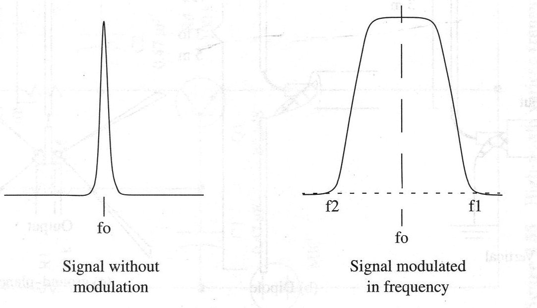
It is important to observe that any signal applied to the varicap will modulate the high-frequency signals in frequency, including stereo multiplexed ones.
Therefore, the circuit described in other project in this site intended to produce an FM multiplex stereo signal can be coupled to this transmitter with no problems.
To drive the transmitter from power supplies plugged to the ac power line, it is important to provide a good, clean circuit. Power supplies must have good filtering and stabilization to avoid noise and hum. Powering the circuit from a battery avoids these problems, but the battery must be able to handle the high current drain of the transmitter.
Auto batteries or nicads are recommended for this task.
We must also remind the reader that the range depends not only on output power but also on the antenna. Three types of antennas that can be used to increase range are shown in Fig. 4.
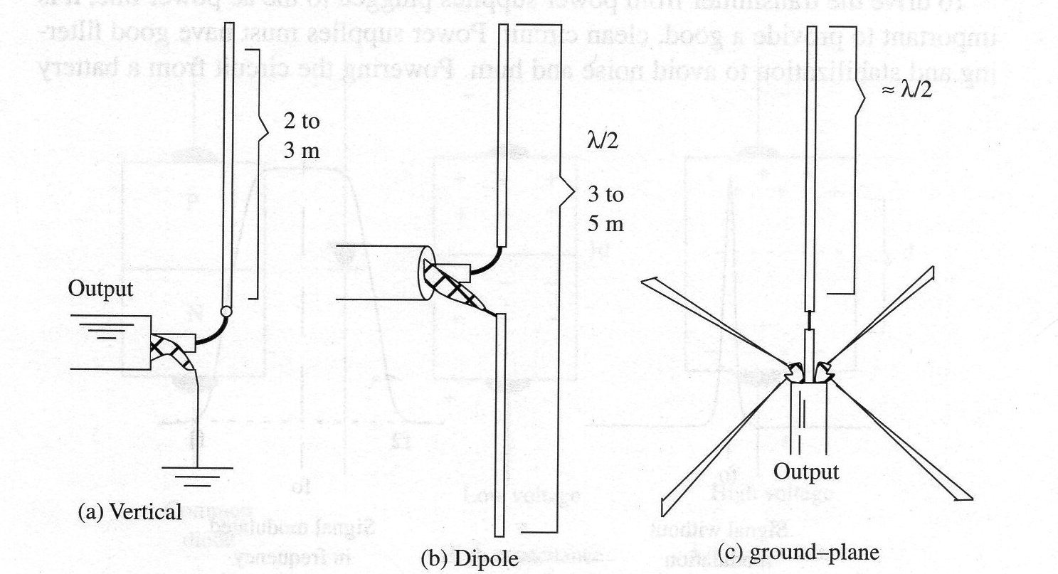
It is important to use a standing wave ratio (SWR) meter to adjust the antenna and cable length. In this way, you can obtain the best performance by, avoiding stationary waves that reduce the output power and overload the output transistors.
Assembly
Figure 5 shows the complete diagram of the high-power varicap transmitter.
The principal components are mounted on a printed circuit board as shown in Fig. 6.
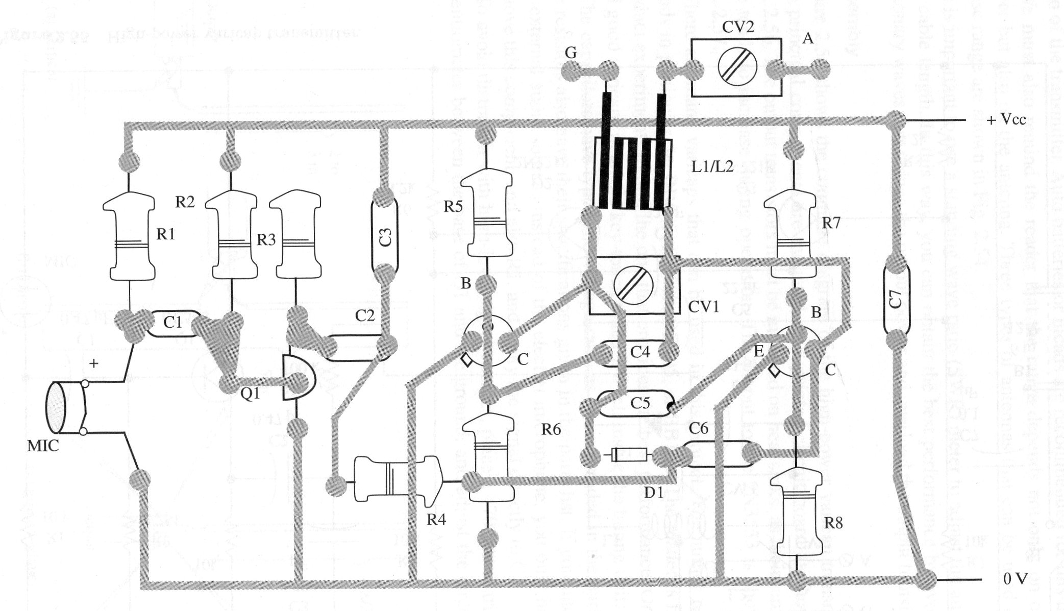
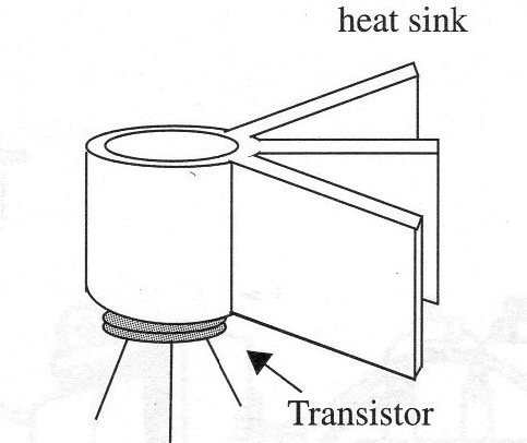
The output transistors must be mounted on heat sinks, as their temperature tends to increase during operation. The pinout to the 2N3553 is shown in Fig. 7.
There are many varicaps that can be used in this project. The author recommends in particular the BB809, BB909, BB405, or BB106. The reader is free to conduct experiments to lind the one that provides the best performance. One can find good varicaps in an old key-touch tuned TV set, inside the tuning unit.
The capacitors have types and voltage rates as recommended in the parts list.
The resistors also have their speciíications given in the parts list. If you intend to use external audio sources instead of the electret microphone, you only have to remove this component, and also R1, and apply the signal directly to Cl.
To avoid distortion with high-level signal sources, place a 470,000 ohm trimmer potentiometer between the base of Q1 and the ground, and adjust the circuit for best performance. Any trimmer capacitor with capacitances in the range between 2-20 and 4-40 pF can be used.
L1 is formed by 3 + 3 turns of AWG 20 to 22 enameled wire wrapped on a 1 cm diameter coreless form (air core). L2 is formed by 3 or 4 turns of the same wire interwoven with Ll. You can use a pencil as a reference for winding these coils. Common plastic covered wire can also be used.
A power supply to this circuit is shown in Fig. 8.
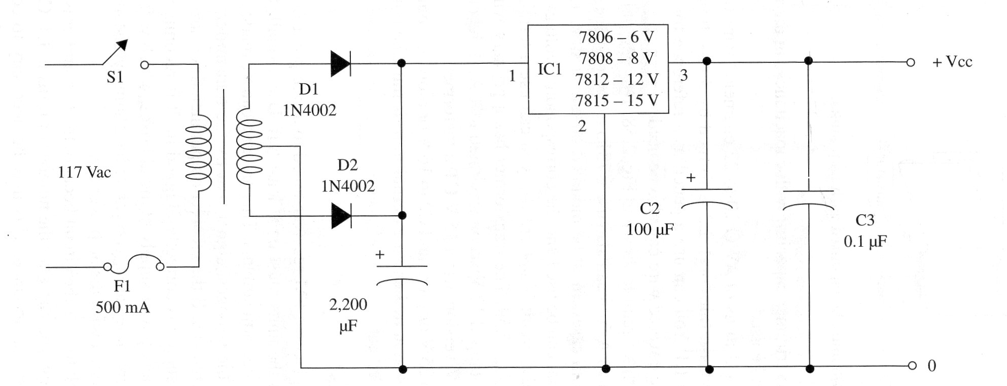
This circuit has a 12 V output with a current up to 1 A. You can also use a 7815 to increase the output voltage to 15 V. The IC, in both cases, must be mounted on a heat sink. The circuit diagram shows the ICS that can be used and the corresponding voltage outputs.
As the power supply circuit is not critical, you can use a terminal strip as its chassis, as shown in Fig. 9.
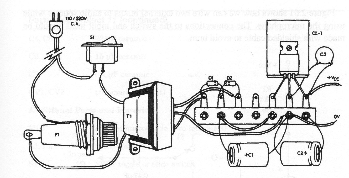
The transformer has a primary Winding rated to 117 Vac, and a center-tapped 12 V secondary rated to 1 A, if the circuit is the 12V version. For the 15 V version, use a 15 V CT transformer.
C1 must be rated to 25 V or more and C2 to 16 V or more. C3 must be ceramic. If the power supply is mounted as an external unit, it must be connected to the transmitter by a shielded cable.
Adjustments and Use
Near the transmitter, place an FM receiver tuned to a free point in the FM band.
The distance between the units must be at least 6 ft. Use a small (8 to 20 inches long) antenna to make the adjustments. This antenna can be made of rigid wire.
Adjust CV to tune the strongest signal sent by the transmitter. Take care that you do not tune to harmonics. If the receiver output includes a strong hum, check to see that the power supply is correctly plugged in. It is recommended that you install the transmitter and power supply in metal boxes, which will shield against hum and other noise. In some cases, you can reduce hum by installing a 0.1 µF 600 V capacitor in parallel with the ac power line.
If you find it difficult to tune the circuit because the transmitter is not operating at the desired frequency, you can alter the number of turns in Ll. Conduct experiments to Hnd the best performance. This may be necessary to compensate for component tolerances and characteristic variations introduced by a particular mounting layout.
After determining the best operational conliguration using the small antenna, you can wire the circuit to an external antenna. Make readjustments to again establish the best performance.
A simple multimeter can be used as a field strength meter as shown in Fig. 10.
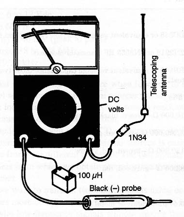
The transmitters trimmer capacitor must be adjusted to highest voltage indication on the multimeter. The multimeter and antenna must be placed 3 or 4 ft away from the transmitters antenna.
Figure 11 shows how we can wire two external inputs to audio sources while using the microphone.
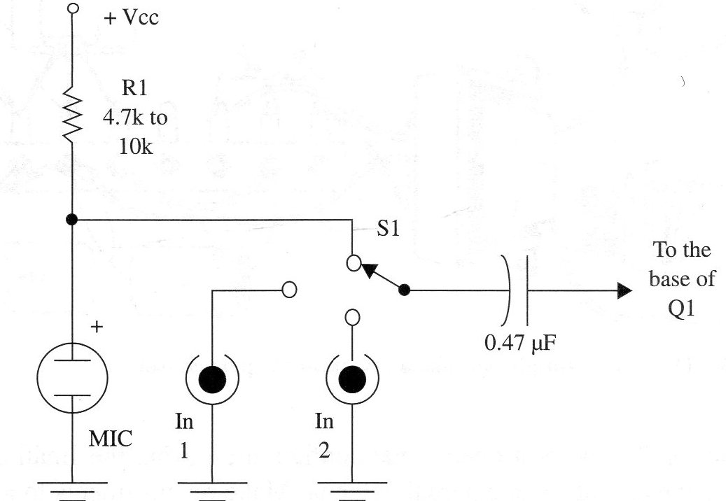
The connections to the switch and input jacks should be made with shielded cable to avoid hum.
Semiconductors
Q1 - BC548 or equivalent general-purpose NPN silicon transistor
Q2, Q3 - 2N2218 or 2N3553 RF transistor (see text)
D1 - BB809 or equivalent variable capacitance diode (varicap) (see text)
Resistors (1/8 W, 5%)
R1, R2, R5, R7 - 10,000 ohm - brown, black, orange
R2 - 2,200,000 ohm - red, red, green
R4 - 120,000 ohm - brown, red, yellow
R6, R8 - 8,200 ohm - gray, red, red
Capacitors
C1, C2 - 0.47 µF ceramic or metal film
C3 - 4,700 pF ceramic
C4, C5 - 22 pF ceramic
C6 - 15 pF ceramic
C7 - 0.1 µF ceramic
CV1, CV2 trimmers (see text)
Additional Parts and Materials
MIC - electret microphone (two terminals)
L1, L2 - coils (see text)
S1 - SPST toggle or slide switch
Printed circuit board, heat sinks for the transistors, shielded cable, metallic box, terminal strip to antenna/ground, telescoping or external antenna, power supply, etc.


