Logic functions are not only important for understanding how microcontrollers work, but can also be used in interfacing under special conditions, for example when there is a latency problem, simultaneous detection of sensor signals, or even the simultaneous triggering of loads .
The microcontroller does not do everything, and there are even cases where it can not do things which are seemingly simple.
The use of logic functions may be necessary and they can be implemented or understood even with simple circuits using relays, such as those described in this article.
Relays can be used to trigger a wide variety of load types: oscillators or indicator LEDs, even small motors or devices connected to the power grid, as shown in Figure 1.
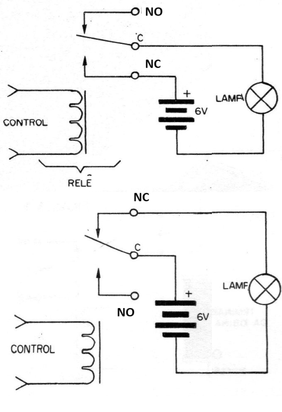
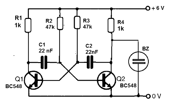
Of course, the lamp can be replaced by other loads, such as an LED in series with a 470 ohm (6V) resistor or an oscillator circuit as shown in Figure 2.
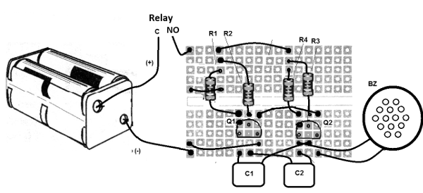
The red terminal on the breadboard assembly goes to the NO contact of the relay as shown in Figure 3.
The circuits:
Next, we give several circuits to simulate common logic functions. The relays can be 5, 6 or 12 V with currents of 20 mA at 100 mA and an appropriate power supply.
a) YES Function
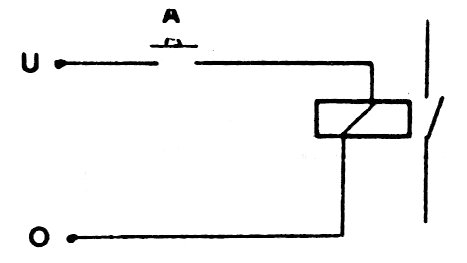
It is the simplest function which is the one that triggers the load if the level of the input signal is 1. That is, a truth table would be:
|
A |
OUT |
|
1 |
0 |
|
2 |
1 |
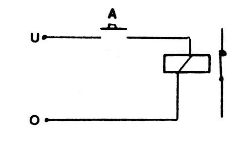
In Figure 4, we have the way to implement this function with a relay: The represented contacts are NO and C.
b) NOT or Inverter Function
In Figure 5, we have the way to implement an inverter using a relay. The used contacts are NC and C. The truth table will be:
|
A |
OUT |
|
1 |
1 |
|
2 |
0 |
c) AND Function
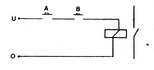
In Figure 6, we have the way to implement the AND function with two inputs, in the case of switches. The switches, in a practical application, can be replaced by sensors.
The truth table for this function is:
|
A |
B |
OUT |
|
0 |
0 |
0 |
|
0 |
1 |
0 |
|
1 |
0 |
0 |
|
1 |
1 |
1 |
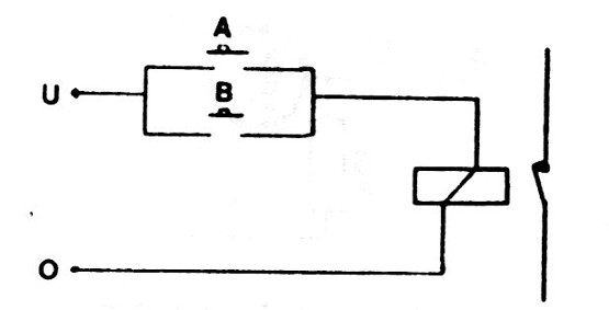
d) OR function
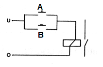
Figure 7 shows how to implement a two-input OR function using a relay. The relay contacts are NO and C. The truth table for this function will be:
|
A |
B |
OUT |
|
0 |
0 |
0 |
|
0 |
1 |
1 |
|
1 |
0 |
1 |
|
1 |
1 |
1 |
e) NAND Function
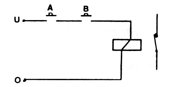
This function is implemented using the contacts C and NC of the relay. In Figure 8, we have the way to connect the sensors or switches and bellow you find the truth table.
|
A |
B |
OUT |
|
0 |
0 |
1 |
|
0 |
1 |
1 |
|
1 |
0 |
1 |
|
1 |
1 |
0 |
f) NOR Function
In this case, the output will be activated (1) when both inputs are disabled, i.e. neither are activated. The circuit is implemented with a relay, as shown in Figure 9. Note that we make use of the contacts NC and C.
The truth table will be as follows:
|
A |
B |
C |
|
0 |
0 |
1 |
|
0 |
1 |
0 |
|
1 |
0 |
0 |
|
1 |
1 |
1 |
g) Exclusive OR Function
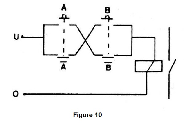
For this function, a bit more sophisticated, we need switches (keys) or double sensors. This is necessary because when one sensor switches on one half the other switches off. For this purpose, we can use an H switch, where the sections will be connected alternately.
The circuit of this function implemented with relays is shown in Figure 10.
The truth table for this function is:
|
A |
B |
OUT |
|
0 |
0 |
0 |
|
0 |
1 |
1 |
|
1 |
0 |
1 |
|
1 |
1 |
0 |
h) Memory or Bistable
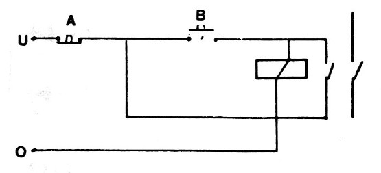
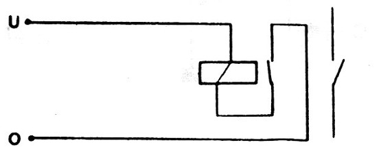
To implement this function we need a relay with double contacts, as shown in Figure 11.
With a pulse produced by B, the relay locks powering the external load (output level 1) and thus remains, even after B is turned off.
To reset the circuit, it must be turned off at A, that is, level 0 at this input.
i) Monostable
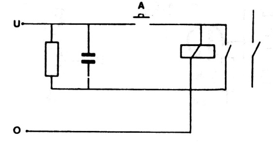
When the input signal disappears, the capacitor keeps the circuit powered for a time which depends on its value. Common 5 to 12 V relays with a few hundred ohms capacitors from 100 uF to 4700 uF can provide periods of up to several seconds. The circuit is shown in Figure 12.
j) Oscillator or clock circuit
We can make a relay oscillate by producing a rectangular signal, taking advantage of the inductance of its coil and capacitance between coils as shown in Figure 13. By connecting a capacitor from 100 nF to 100 uF in parallel with the coil, we can reduce the frequency of the generated signal .
Conclusion:
In the last century, one of the pioneers of computing built a computer using only relays. Although the calculations performed were very simple, we must not forget to consider the circuit used as a digital application.
Nowadays, the relays are used for many other purposes and indispensable in shields for microcontrollers. However, they can still be used for didactic and experimental purposes, as we have seen in this article, and even solving very simple automation problems which do not require the use of a microcontroller.
In fact, many think of the microcontroller as a solution to everything. But, there are cases where it is a cannon to kill a mosquito. In this case, simple things, such as relays, may be the solution.


