Heat loses in electronic appliances or at your home can be easily detected using this simple device. You can also use this circuit to detect temperature variations in experiments involving biology, chemistry or physics.
Critical points in a project as hot resistors, transistor or other components who convert electrical power into heat and cause many problems can be also detected using this circuit.
But the particular attraction in this circuit is that temperature sensing device (the diode) can be quite remote from the indicating device (the ammeter). Thus the sensor can be placed outdoors to detect outside temperature changes, coupled by two thin insulated wires to the detector circuit indoors.
As the amount of current flowing through a circuit depends upon the amount of voltage applied and also the amount of resistance in the circuit, any point with anormal resistance will produce heat enough to cause damages to the components.
The proposed circuit shows when the temperature in any point of a circuit rises to values high enough to manace components.
The circuit can also be used at home to detect heat loses. Invisible holes or apertures in windows, doors or in the floor causes heat loses that increases the amount of power necessary to sustain the desired indoor temperature in any ambient.
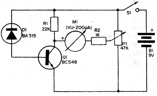
The circuit uses as a passive temperature transducer a common silicon diode. As the amount of current through a diode reverse biased depends upon the temperature of the junction, this kind of component can be used as a sensitive detector to temperature variations.
The amount of current through the diode is very low so we need amplification. The current is amplified by a transistor driving a microammeter. P1 adjusts the zero point to the center of the scale, as the needle has to oscilate right and left, according the temperature goes up and down.
Figure 1 shows the schematic diagram of the heat detector.

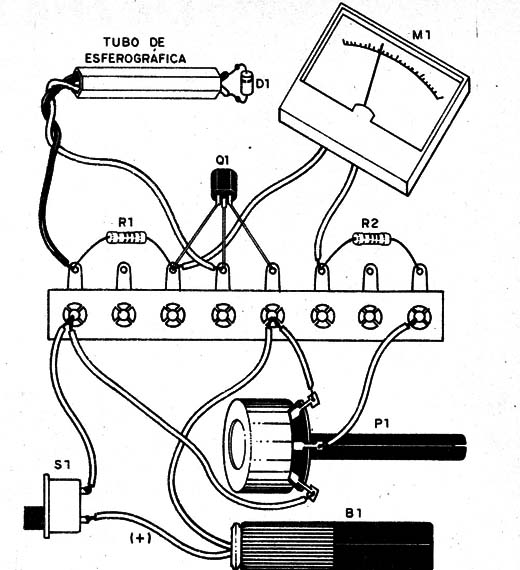
Components are placed on a terminal strip used as chassi is shown at figure 2.

The sensor, any common silicon diode, is mounted at the end of a pen tube.
Take care with the position of the diode since it is a polarized component as the battery and the transistor. Depending on the application, you can protect the diode with an epoxi cover.
Any microammeter with current ranges from 100 to 500 µA can be used in this project. You can find ammeters in non-functioning old amplifiers were they are used as VU-meters.
Now you are going to test the circuit: adjust P1 to have a center scale position of the needle in M1.
Put the sensor between your fingers and wait about 40 or 50 seconds to achieve the termal equilibrium. The heat of your body will be detected and you will see the ammeter needle moviment indicates the temperature rise.
Don't touch the terminals of the diode as this will cause modification of the resistance with a false indication temperature variation (protect the diode with an epoxi coat if necessary).
Using the detector: put the sensor near (don't touch) the place where you want to detect heat variations and wait about 40 seconds or more to allow the sensor to change its own temperature according the ambient and observe the ammeter needle.
Q1 - general purpose NPN silicon transistor
D1 - 1N914 or equivalent - general purpose silicon diode
R1 - 22,000 Ω, 1/4-watt, 5% - resistor
R2 - 1,000 Ω, 1/4-watt, 5% - resistor
P1 - 47,000 Ω - potentiometer
S1 - SPST - slide or toggle switch
B1 - 9 V - battery
M1 - 0 - 200 µA - microammeter - see text


