You can use this circuit to have a voltage visual indication in experiments involving different kind of sensors.
Four LEDs form a "bargraph" scale indicating the amount of voltage at the input of the circuit in a range between 0 and 6 volt.
Bio-voltages, voltages produced by experimental or alternative cells, experimental photo-cells and fuel cells can be indicated by this voltmeter.
The circuit uses a LM139 or CA139 integrated circuit and also equivalents. These ICs contains four voltage comparators that can drive directly four LEDs when powered from a 6 V supply.
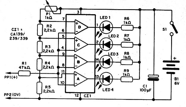
Operation is easy to understand: the voltage divider formed by R2, R3, R4, R5 and P1 fix a reference voltage applied to the non-inverting input of each comparator.
When the voltage applied to the input of the circuit, which is wired to the inverting inputs off all comparators, reaches the correspondent reference voltage, the comparator triggers on and its output, which was at the HI logic level, goes to the LOW logic level and the correspondent LED turns on.
Since the reference voltages at each comparator are in sequence, each LED turns on in a different input voltage.
Figure 1 shows the schematic diagram of the digital voltmeter.

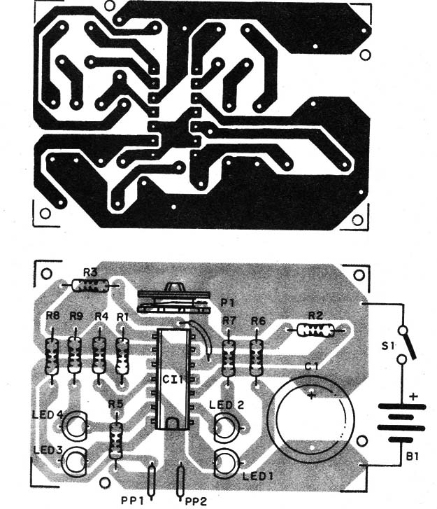
The components are placed on a printed circuit board as shown in figure 2.

Positions of the LEDs and electrolytic capacitors should be observed as they are polarized components.
The circuit can be housed into a small plastic box and powered from 4 AA cells. The LEDs should be placed in a manner that allows to observe them when glowing.
Connection to the external circuits or components under test can be made using two common probes. One of them should be red (PP1) to the positive pole, and the other black (PP2) to the negative pole.
Using the voltmeter: connect the probes to the circut and observe the LEDs. The number of LEDs glowing up is proportional to the amount of voltage in the tested circuit or device in a scale between 0 and 6 volt. We can say that each LED corresponds to a range of voltage of about 1.5 volts.
So, one LED glowing means a voltage between 1,5 and 3 V. Two LEDs a voltage between 3 and 4,5 V and four LEDs between 4,5 and 6 V.
P.S. Don't use this circuit to detect or measure voltages higher than 6 V. The integrated circuit can be damaged.
IC1 - CA139, CA239, CA339 or LM139, LM239, LM339 - Integrated Circuit - see text - four voltage comparators
LED1, LED2, LED3, LED4 - Common red LEDs
R1 - 47,000 ohm, 1/4-watt, 5% - resistor
R2, R3, R4, R5 - 2,200 ohm, 1/4-watt, 5% - resistors
R6, R7, R8, R9 - 1,000 ohm, 1/4-watt, 5% - resistors
P1 - 1,000 ohm - trimmer potentiometer
C1 - 100 µF/12 WVDC - electrolytic capacitor
PP1, PP2 - Common red and black probes
S1 - SPST - slide or toggle switch
B1 - 6 V - 4 AA cells


