With only two transistors and a few additional components we can make two LEDs flash alternately. The device can be used as a psychological alarm, in robots and other mechatronic devices or in models
The two LEDs are activated alternately switching the two any type transistors. TheOn-Off cycle of each LED is determined both by the values of capacitors used as the setting of a potentiometer.
The trimpot or potentiometer can have their values in the range of 22 K Ω to 100 K Ω and capacitors may have values between 2.2 µF and 100 µF. The higher the value of the capacitors greater is the interval between blinks or lower the operating frequency of the circuit.
The transistors may be of any type NPN general purpose, including recovered from waste.
Power should be done with voltages from 6 to 9 V obtained from batteries or cells. The required current is low, which ensures good durability to the batteries or cells.
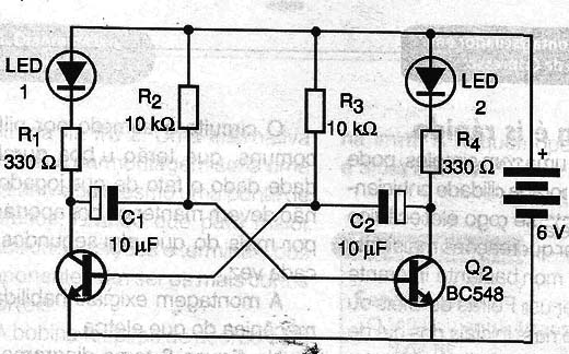
In Figure 1 we have the complete diagram of this unit.

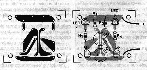
Figure 2 show the arrangement of components in a small printed circuit board but the assembly can be made us in a less formal manner with a terminal strip.

With a very compact mounting the unit can be installed in a small plastic box.
When mounting note the LED position, transistors and capacitors that are polarized components.
To prove the device and use just put the batteries in the holder. As there is no main switch the LEDs should start flashing immediately. If you want to change the frequency change the capacitors.
In trimpot potentiometer can change the frequency or lighting timing of each LED.
For connecting more LEDs they can be in series in each branch of the circuit.
However, the limit of three LEDs as the drive voltage of the red type is 1.6 V which means that the operation is normal should increase the voltage to 9 V
If we connect the LEDs in parallel we must put in series with each a 330 Ω resistor and in this case is not recommend an amount greater than 3 per transistor.
Semiconductors:
Q1, Q2 - BC548 or equivalent - any general purpose NPN transistor
LED1, LED2 – Common LEDs - any color
Resistors: (1/8 W, 5%)
R1, R4 - 330 Ω - orange, orange, brown
R2, R3 - 10 k Ω - brown, black, orange
P1 - 100 k Ω - trimpot or pot
Capacitors:
C1, C2 - 10 µF / 6 V - Electrolytic
Miscellaneous:
B1 - 6 V - 4 small batteries
Terminal strip, cells holder, wires, etc.


