We are going to describe a simple device able to detect water leakage points, rain, places affected by water infiltration, etc. To science fairs and Technology Education, this circuit can detect the moment in which water begins to appear in a certain point of the experiment. In a distillation experiment, for instance, the device can be used to advise when the production of water starts.
Note: this project was included in my book Science Fair and Technology Education Projects published in USA.
The circuit can also be used to demonstrate that the human body is an electric conductor. The circuit produces an audible sound when triggered. By the sound, we can evaluate the degree of humidity of the body under test.
The sensor is formed by two small conducting sponges, placed at the bottom of the plastic box in which the circuit is housed. In contact with a wall, soil or person, the current flowing between the sponges indicates the amount of humidity.
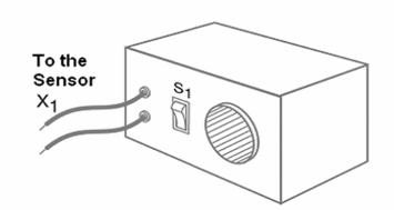
The device is powered from common cells and a small loudspeaker is the sound transducer. No adjustment is needed and using it is very easy: you just have to place the sensor in contact with the point where you want to detect humidity. The device can be housed in a small plastic box as figure 1 shows.

How it Works
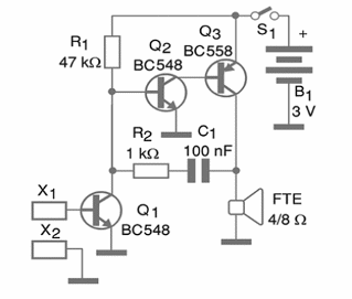
The circuit is formed by two complementary transistors (NPN-PNP) that work only when the base of Q2 is direct biased. The bias comes from Q1, which conducts the current only in the presence of humidity in the sensor. The sensor is formed by two small conductive sponges placed near one another.
The sponges are normally found in anti-static semiconductor protection package wrappings, like memories, microprocessors and CMOS ICs. The sponges can be glued to a PCB or to the bottom of the plastic box. A set of two metallic grids with a paper or a piece of tissue can be another sensor that detects water or rain.
The running frequency of the oscillator is given by R1 and C1 and the resistance between the emitter and the collector of Q1. Since this resistance depends on the humidity on the sensor, we have some possibilities to consider: in one extreme, a low tone represents a very high resistance in the sensor and so, it is dry or placed on a dry location.
In the other extreme, a high tone represents a low resistance, or a high degree of humidity. This means that the sensor is placed on a wet location, indicating a water leakage or some other water presence.
The circuit is powered by common AA cells and the S1 (on/off switch) is optional. The power drain when the sensor is dry is very low.
Building
Figure 21 shows the schematic diagram of the humidity detector.

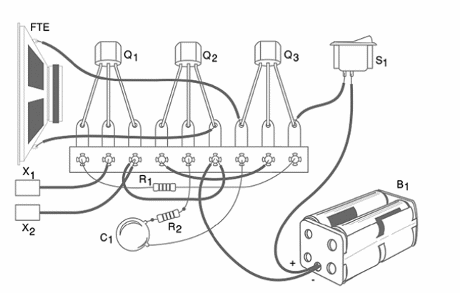
Figure 3 shows the components placement on a terminal strip.

The resistors are 1/8 W or 1/4 W types with any tolerance. The capacitor is a polyester or ceramic type with a voltage rate starting from 50 V. The loudspeaker is a small type (2.5 cm to 10 cm) retired from an old non functioning appliance, like a transistor radio, recorder or sound equipment. Choose the plastic box according to the loudspeaker’s dimensions. The cells are placed in a proper holder.
Testing and Using
Install the cells in the cells holder and turn on S1. Then, touch any wet place (wall, soil, wet paper, etc) with the sensor. The device will produce a sound according to the degree of humidity: low tone for dry or slightly wet and high tone for very wet.
What to Explain
Explain that pure water is an isolator, but in natural conditions, the water has a large amount of impurities. These impurities solved in the water make it a conductive media. So, wet places present a low resistance to the electric current.
Placing your fingers on the sensor, the device will also sound, showing that your skin is conductive. You can show that if your fingers are wet the tone is higher. You can use this experiment to show how dangerous a shock is when you are wet. Explain also that a low tone is caused by a high resistance between the sponges of the sensor, associated to a dry object.
Suggestions:
Replace the sensor with two metal plates. You can convert the device into a lie detector. The small changes in the tone when someone with the fingers in the sensor is interrogated can reveal a lie. The explanation is that emotional changes can also cause changes in the resistance due to the action of the sudoriferous glands. If you cannot find the conductive sponges, make a sensor using metal plates.
Replacing the sensor by an LDR (light dependant resistor), you can convert the device into a sensitive light detector. The circuit will sound when light falls onto the sensor.
Semiconductors:
Q1, Q2—BC548 or equivalent—general purpose silicon NPN transistor
Q3—BC558 or equivalent—general purpose silicon PNP transistor
Resistors: (1/8 W, 5%)
R1—47 k?—yellow, violet, orange
R2—1 k ?—brown, black, red
Capacitors:
C1—100 nF (104 or 0.1) - ceramic or polyester
Other:
FTE—4 to 8 ohm—2.5 cm to 10 cm loudspeaker
S1—On/off switch
B1—3 V—2 AA cells with holder
X1, X2—sensors—see previous text
Terminal strip or printed circuit board (PCB), plastic box, wires, solder, etc.


