Signal tracing by means of a signal tracer offers a valuable method for servicing a variety of electronic equipment.
This method is often employed when a circuit is not completely dead, but rather malfunctioning. AM and FM receivers, CD players, multimedia amplifiers, TV sets, etc., can be serviced using this simple signal tracer.
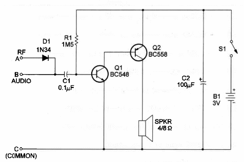
The circuit we show here consists of a two-stage direct-coupled transistor amplifier. The circuit has two inputs. When the probe is used in the RF mode the detector diode is inserted into the circuit. When the probe is used in the audio mode the signal is applied directly to the base of the first transistor (Q1).
As the circuit has a low-power output, a gain control is not used.
The circuit is powered from two AA cells, and current drain is only few milliamperes. Since the circuit draws such low current, long battery life can be expected.
Figure 1 shows the schematic diagram of the signal tracer.

R1 determines the gain of the amplifier stage and can be altered to get better performance depending on the transistors used.
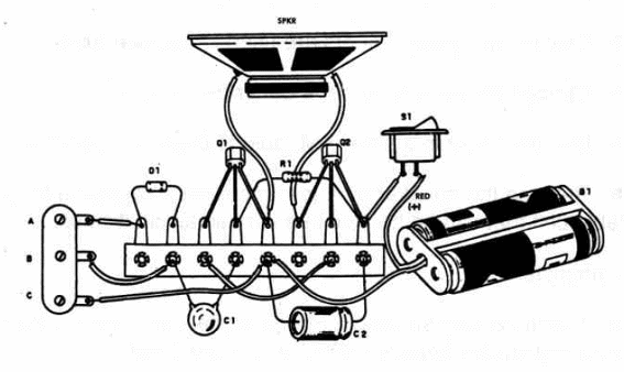
Figure 2 shows the signal tracer mounted on a terminal strip, which is used as a chassis.

Take care with the transistors; one is an NPN and the other is a PNP. It you switch one with the other the circuit will not work.
This project can be housed in a small plastic box.
The size of the plastic box is determined by the speaker size. Position of the polarized pieces should be observed.
Signal Tracer
Q1 - BC548 general-purpose NPN silicon transistor
Q2 - BC558 general-purpose PNP silicon transistor
D1 - 1N34 or equivalent - any germanium transistor
R1 - 1,500,000 ohm, 1/4W, 5% resistor
C1 - 0.1 µF ceramic or metal film capacitor
C2 - 100 µF, 6 WVDC electrolytic capacitor
SPKR - 4/8 Ω - 2 or 4 in. small loudspeaker
S1 - SPST slide or toggle switch
B1 - 3V - two AA cells
Ideas to Explore
To learn more about the circuit or to get better performance:
Explain how signal tracers are used for service work.
Change R1 value to achieve better performance.
Use the tracer in a small AM radio to study its operation.
0 Replace the speaker by a low-impedance earphone to get a portable unit that can be housed in a very small plastic box.
Science projects:
The tracer can be used to detect signals produced in experiments involving current fields, as described in others projects in thes section
The tracer can be used as an experimental audioamplifier with transducers such as piezoelectric pickups or microphones.


