
ART2950S ART163
An astable multivibrator using a 555 timer does not have an exact 50% duty cycle, as shown in Figure 1, because the time at the high level is given by the charging of the capacitor through two resistors (Ra+Rb) and the time at the low level is given by the discharge through Rb.
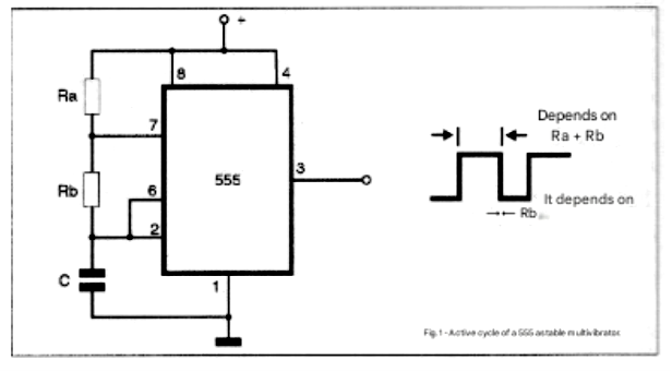
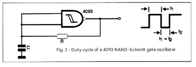
Therefore, however small Rb is in relation to Ra, we cannot "zero" this component, and thus the duty cycle is no longer exactly 50%. On the other hand, a circuit like the one in Figure 2, where we use a 4093, has a duty cycle of 50% because the times at the high and low levels are determined by the charging and discharging of the capacitor through the resistor.
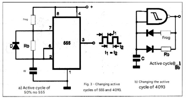
We can alter the duty cycles of these two types of oscillators using diodes that change the path of the capacitor's charging and discharging current, allowing us to use different resistors for the process, as shown in Figure 3.
What we propose in this article is something different: using a common oscillator to drive a 4017 counter that will be programmed to modify the duty cycle according to the frequency division. By choosing the appropriate oscillator frequency and the value of the division quotient, we can obtain signals with frequencies and duty cycles according to the desired purpose. In what types of applications can we use this circuit?
With modifications ranging from using a fixed duty cycle program to eliminating the inverter at the output, we can have the following possible uses for the basic circuit presented:
* Signaling system where the oscillator drives a lamp that will give short-duration pulses, with greater energy savings.
* Switched-mode power supplies where the output voltage can be determined by the duty cycle duration.
* Timers where the activation time (pulse duration) can be programmed according to the activation interval (interval between pulses).
* Power controls where the power applied to a load via a triac or SCR depends on the conduction time and therefore the duty cycle.
Obviously, how to carry out each project depends on the reader. The basic configuration of the oscillator with selectable duty cycle is given below.
HOW IT WORKS
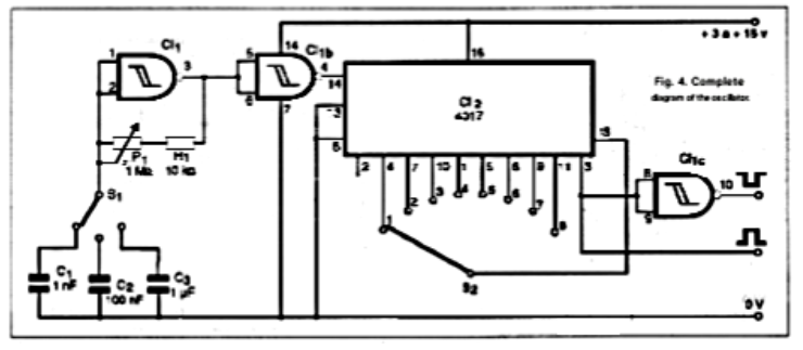
The oscillator that provides the signal to the circuit is built around one of the four trigger gates of a 4093 IC. The capacitor that determines the time range is selectable via S1. Obviously, depending on the application, a fixed capacitor can be used. In fact, the indicated values are not the limits allowed. Values in the range of 200 pF to 1000 uF can be used. Fine frequency adjustment is done by potentiometer P1. Again, depending on the application, a fixed resistor can be used.
What we can say is that, with a 12-volt power supply, the 4093 should oscillate at frequencies up to approximately 4 MHz. An additional gate of the 4093 IC is used to function as a buffer, directly driving the clock input, which is pin 14 of the 4017 IC. The 4017 circuit consists of a counter/divider by 10, where we have a high-level output of 10 at each input pulse.
By feeding back the last used output to the reset input, we can count down to smaller values. For example, if we connect the eighth output to the Reset, we will count down to 7. An important characteristic of the circuit when we perform this smaller count is that the duty cycle of the input signal is altered, and that is exactly what we want. Thus, while dividing the frequency, we alter the duty cycle of the signal in a perfectly predictable way. In our case, we then have the following possibilities selectable by switch S2.
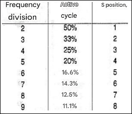
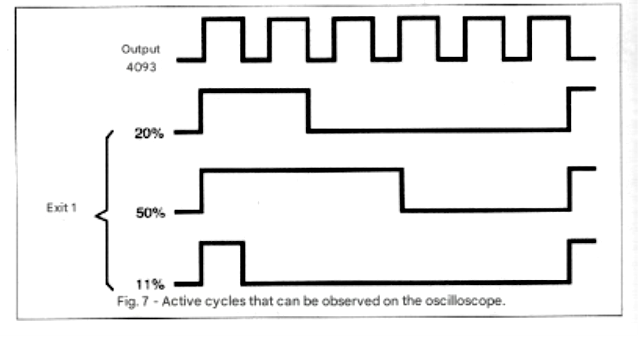
An interesting possibility for the project is to connect more than one 4017 to further modify the obtained cycles. A third gate of the 4093 is used to create an inverter, allowing for complementary duty cycles to those indicated. Thus, with the switch in position 4, we can obtain duty cycles of 20% and also 80% on this inverter gate. The circuit is CMOS and can be powered with voltages from 3 to 15 volts.
ASSEMBLY
Figure 4 shows the complete diagram of the basic circuit which, depending on the application, may obviously be part of other equipment.
If the reader wants a standalone assembly on a printed circuit board, the component layout is shown in Figure 5.
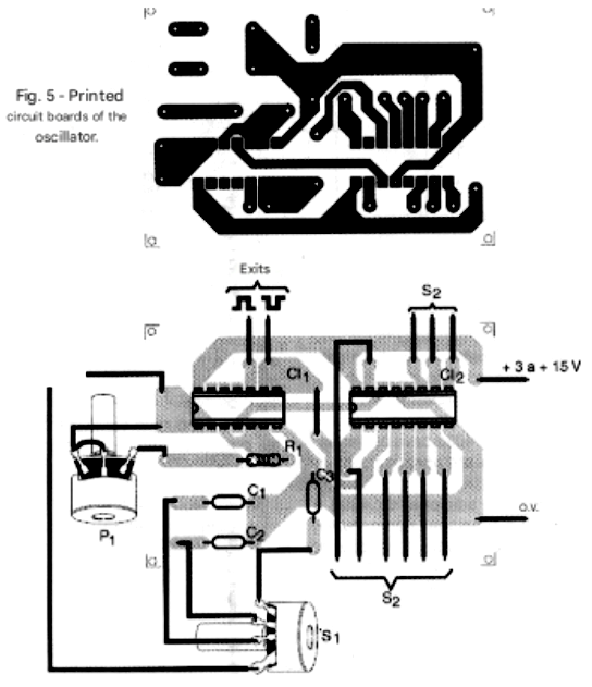
For greater safety and ease of replacement, integrated circuits can be mounted in DIL sockets. Remember that at higher frequencies, care must be taken with the component arrangement to avoid operational instabilities. The capacitors can be ceramic or polyester, and the resistor is 1/8W. The potentiometer or trimpot is optional; if using a potentiometer, short wires should be used if the operating frequency is above 1 MHz. The switches can be rotary type, and in the case of S2, one can even be salvaged from old equipment. Old manual voltage stabilizers used in televisions used these switches, and perhaps, with luck, the reader can find one to remove the switch from (although its relatively large size slightly affects the compactness of the project).
Another possibility to eliminate the use of S2 is to use a bar of micro-switches that can then be activated with the tip of a pen, as shown in Figure 6.
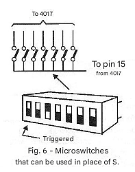
In this case, obviously, the reader must first obtain the switch bar and modify the printed circuit board design to assemble it alongside IC-2.
TESTING AND USE
If the reader has an oscilloscope, it will be easy to verify the circuit's operation and even measure the duty cycle of the generated signals, as well as their frequency. With a dual-trace or channel oscilloscope, it is possible to compare the signals from the oscillator output with the 4093 and the circuit itself, as shown in Figure 7.
Readers working with digital projects can even use this circuit as a test oscillator with selectable duty cycles for equipment testing.
PROJECT SUGGESTION
Figure 8 shows a final application based on this project where we have a signaling lamp that produces short-duration pulses (11.1% duty cycle) in order to obtain a low-power condition.
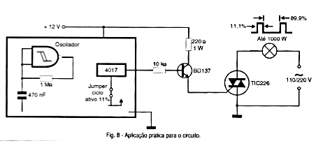
The circuit is powered by the mains electricity supply and can control standard garage door exit lights or even construction site lights up to about 200 watts without major problems. The circuit can operate on both 110V and 220V mains, simply by using the appropriate transformer and SCR. For lamps above 40 watts, the SCR must be fitted with a heat sink. Note that this circuit is directly connected to the mains electricity supply and therefore special care must be taken with insulation and its housing in a closed box.
PARTS LIST
Semiconductors:
IC-1 - 4093 - CMOS integrated circuit
IC-2 - 4017 - CMOS integrated circuit
Resistors: (1/8W, 5%)
R1 - 10 k ohms
P1 - 1 M ohms - trimpot or potentiometer
Capacitors:
C1 - 1 nF - ceramic or polyester
C2 - 100 nF - ceramic or polyester
C3 - 1 uF - polyester or electrolytic
Miscellaneous:
S1 - 1-pole x 3-position rotary switch
S2 - 1-pole x 8-position rotary switch or dip-switch - see text
Printed circuit board, sockets for the integrated circuits, buttons for the switches, wires, solder, etc.


